An Inductor for Partially Incrementally Formed Bimetallic Composite Pipe

A bimetal composite tube and incremental forming technology, applied in the field of bimetal tube forming, can solve the problems of uneven distribution of electromagnetic force, sparse magnetic lines of force, damage to composite interface performance, etc. The effect of reducing the degree of metallurgy and improving the metallurgical recombination rate

Active Publication Date: 2015-08-19
HARBIN INST OF TECH
View PDF4 Cites 0 Cited by
  • Summary
  • Abstract
  • Description
  • Claims
  • Application Information

AI Technical Summary

Problems solved by technology

Depend on Figure 4 It can be seen that since the longitudinal section of the working area is straight, the configuration of the outer tube blank in the previous compounding step changes, and at this time there is a large difference in the radial gap between the sensor working area and the outer tube blank , thus changing the density of the magnetic field lines in the working area, making the distribution of the electromagnetic force extremely uneven, which in turn leads to the problem of uncoordinated deformation of the composite pipe fittings: the large radial gap in the transition zone 7 leads to sparse magnetic field lines, and the radial electromagnetic force received It is obviously smaller than the electromagnetic force received by the deformation zone 9, so the deformation zone 9 preferentially undergoes plastic deformation, and the transition zone 7 is driven to deform and fit the inner tube blank, which finally leads to radial deformation of the bimetallic composite tube blank along the axial direction. Evenly distributed
In addition, the deformation coordination problem caused by this conventional inductor can also lead to a low metallurgical recombination rate
This is because the deformation zone 9 hits the inner tube blank in a nearly vertical manner, and it is impossible to obtain a better match between the collision angle and the collision speed. Finally, the interlayer bonding method of the bimetallic composite tube blank is mainly mechanical bonding. Composite interface performance will limit the scope of use of bimetallic composite pipe fittings

Method used


Image

  • An Inductor for Partially Incrementally Formed Bimetallic Composite Pipe
  • An Inductor for Partially Incrementally Formed Bimetallic Composite Pipe
  • An Inductor for Partially Incrementally Formed Bimetallic Composite Pipe

Examples


specific Embodiment approach 1

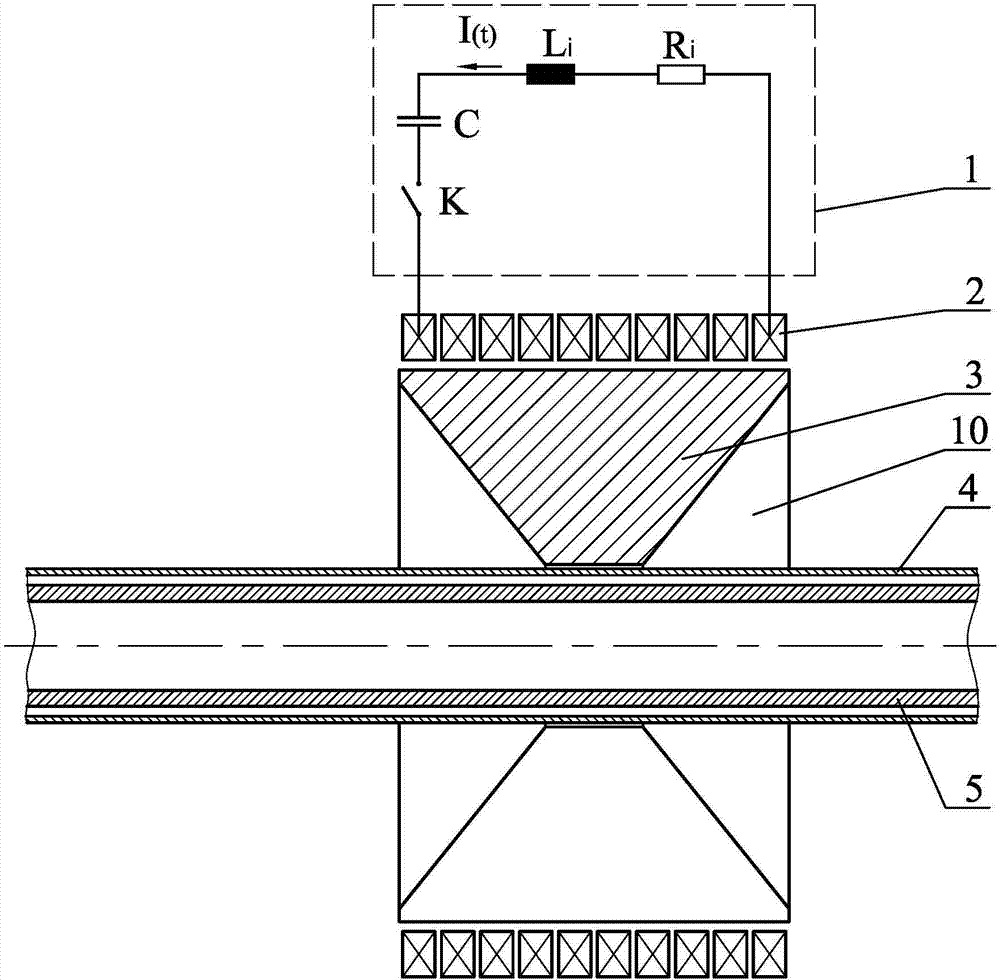
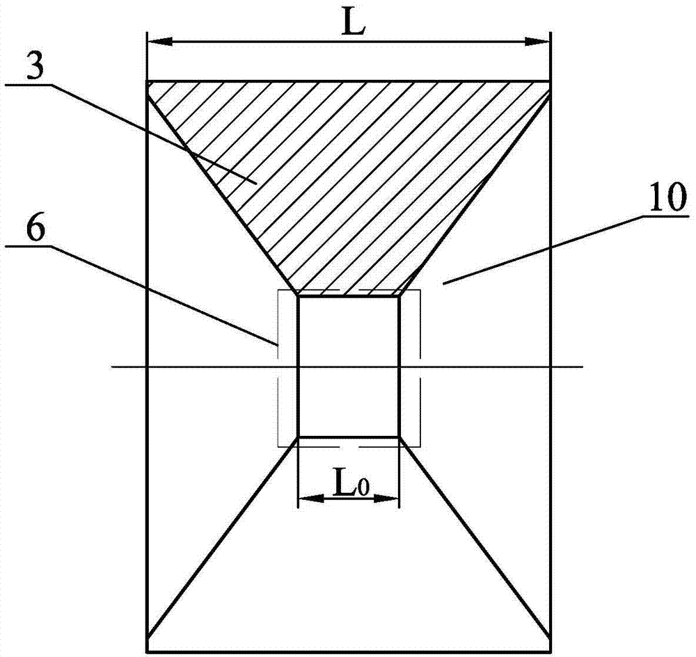
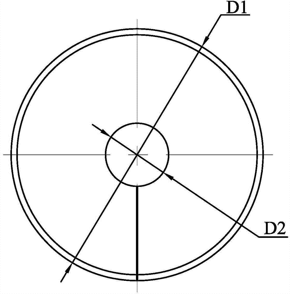
[0020] Specific implementation mode one: combine Figure 7 ~ Figure 10 Explain, the inductor of a bimetallic composite pipe that is progressively formed by partition in this embodiment, the shape of the inductor of the bimetallic composite pipe that is incrementally formed by partition is a cylinder 13, and the two ends of the cylinder 13 are respectively along the axial direction There is a truncated conical groove 10 processed in the direction, and the middle part of the cylinder 13 is processed with an assembly hole communicating with the two truncated conical grooves 10. The assembly hole is coaxially arranged with the two truncated circular grooves 10. The enclosed area is the working area 6. On the side wall of the cylinder 13, there is a long slit 14 communicated with the assembly hole in the radial direction. The small-diameter end of the truncated hole 11 coincides with the large-diameter end of the truncated hole 12, and the large-diameter end of the truncated hole 1...

specific Embodiment approach 2

[0028] Specific implementation mode two: combination Figure 7 Note that the axial length L2 of the truncated cone-shaped hole 12 in this embodiment is 2 mm to 6 mm. The undisclosed technical features in this embodiment are the same as those in the first embodiment.

specific Embodiment approach 3

[0029] Specific implementation mode three: combination Figure 7 Illustrate, the junction of the large frustum-shaped hole 11 and the small frustum-shaped hole 12 in this embodiment is provided with a large transition fillet, the radius of curvature of the large transition fillet is R1, R1=20mm, the large frustum-shaped hole 11 and the adjacent The junction of the frustum-shaped groove 10 and the connection between the small frustum-shaped hole 12 and the adjacent frustum-shaped groove 10 are respectively provided with a small transition fillet, and the radius of curvature of the small transition fillet is R2, R2=1mm. The undisclosed technical features in this embodiment are the same as those in the first embodiment.

[0030]The setting of the β angle is used to preferentially deform the transition zone 7; the setting of the α angle makes the radial gap between the inductor and the outer tube blank 4 gradually increase from right to left, forming a force that gradually decreas...


PUM

PropertyMeasurementUnit
lengthaaaaaaaaaa

Abstract

The invention provides an inductor for divisionally and incrementally forming a bimetal composite pipe, which belongs to the technical field of forming of the bimetal composite pipe and aims to improve the divisional and incremental forming composite rate of a bimetal composite pipe fitting and the radial uniformity of the bimetal composite pipe fitting. According to the inductor, one assembling hole communicated with two circular-platform-shaped grooves is machined in the middle of a cylinder; a region around the assembling hole is a working region; the assembling hole is composed of a large circular-platform-shaped hole and a small circular-platform-shaped hole; the small-diameter end of the large circular-platform-shaped hole is overlapped with the large-diameter end of the small circular-platform-shaped hole; the large-diameter end of the large circular-platform-shaped hole and the small-diameter end of the small circular-platform-shaped hole are located at the two ends of the assembling hole respectively; an included angle between the generatrix of the large circular-platform-shaped hole and the horizontal plane is alpha; an included angle between the generatrix of the small circular-platform-shaped hole and the horizontal plane is beta; the axial length of the large circular-platform-shaped hole is L1 and the axial length of the small circular-platform-shaped hole is L2; the axial length of the assembling hole is L0. The inductor for divisionally and incrementally forming the bimetal composite pipe is used for compounding the bimetal composite pipe fitting.

Description

technical field [0001] The invention relates to an inductor for forming a bimetal composite pipe, which belongs to the technical field of bimetal pipe forming. Background technique [0002] Bimetallic pipe fittings are composed of an inner tube blank and an outer tube blank, and the inner and outer tube blanks are tightly combined. When bearing the external load, the inner tube blank and the outer tube blank deform at the same time. Bimetallic pipe fittings can be divided into mechanical bonding and metallurgical bonding according to the bonding method between the pipe layers. The former is also called double-layer pipe fittings, and the latter is also called bimetallic composite pipe fittings. The material of the inner tube blank and the outer tube blank can be selected according to the working conditions. Therefore, the bimetallic pipe fittings can not only have the required high strength, but also have excellent corrosion resistance and wear resistance. and other proper...

Claims


Application Information

Patent Timeline
Patent Type & Authority Patents(China)
IPC IPC(8): B21D26/14
Inventor 于海平范治松李春峰
Owner HARBIN INST OF TECH
Why Eureka
Try Eureka