A precision forging device and method for a spiral bevel gear

A gear precision and spiral bevel technology, which is applied in the field of spiral bevel gear precision forging and spiral bevel gear, can solve the problems of difficult demoulding, difficult mold filling, and large metal forming resistance, and achieve the effect of reducing the difficulty of mold filling

Inactive Publication Date: 2016-08-17
CHINA AGRI UNIV
View PDF9 Cites 0 Cited by
  • Summary
  • Abstract
  • Description
  • Claims
  • Application Information

AI Technical Summary

Problems solved by technology

[0004] The shape of the active spiral bevel gear is complex, and the pitch line of the tooth surface is a helical line with a large angle, which makes the metal forming resistance large and the mold filling difficult during the precision forging process.
At the same time, the large helix angle of the active spiral bevel gear makes it difficult to demould after forming, so it is necessary to find a method that can smoothly fill the cavity during the forming process and successfully demould after forming

Method used


Image

  • A precision forging device and method for a spiral bevel gear
  • A precision forging device and method for a spiral bevel gear
  • A precision forging device and method for a spiral bevel gear

Examples


Embodiment Construction

[0035] The specific implementation manners of the present invention will be further described in detail below in conjunction with the accompanying drawings and examples. The following examples are used to illustrate the present invention, but are not intended to limit the scope of the present invention.

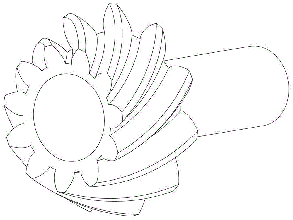
[0036] A precision forging device for spiral bevel gears of the present invention is mainly used for producing such as figure 1 The spiral bevel gear shown. It includes a mold base, a punch 21 , a tooth mold 22 , a lower mold, an elastic member, a rack 51 , a spur gear 52 , a driving spur gear 55 and a driven spur gear 54 .

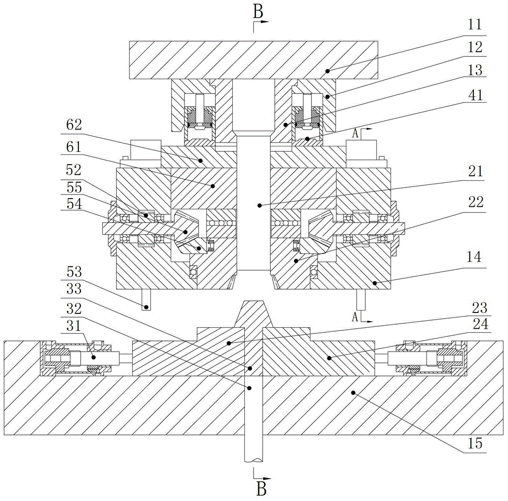
[0037] Such as figure 2 Shown, in the embodiment of the present invention, wherein, formwork is the main body that connects each component, and it comprises upper template 11, lower template 15, pressing plate 62, upper mold supporting device 14, guide post 16 and guide sleeve 17.

[0038] A preferred embodiment is that the inventive precision forgin...


PUM


Abstract

The invention relates to the field of spiral bevel gears, in particular to the field of precision forging of spiral bevel gears. The precision forging device comprises a die set, a convex die, a toothed die, a lower die, an elastic part, a rack, a straight toothed spur gear, a driving straight toothed bevel gear and a driven straight toothed bevel gear, wherein the die set serves as the main body for connecting the parts, the lower die is arranged under the toothed die, the convex die is arranged on the upper part of the toothed die, the lower die, the convex die and the toothed die are closed to form a hermetic cavity, a retaining mechanism is arranged between the driven straight toothed bevel gear and the toothed die to enable the driven straight toothed bevel gear to only drive the toothed die to rotate in one direction, the driving straight toothed bevel gear is meshed with the driven straight toothed bevel gear and is coaxially connected with the straight toothed spur gear, the straight toothed spur gear is meshed with the rack, and the elastic part is arranged above the rack. The precision forging device and the precision forging method realize that the toothed die only rotates during demolding and does not rotate during die assembling and forge piece forming, so that the die filling difficulty and demolding difficulty after forming of a spiral bevel gear in the precision forging process are reduced; the purposes that a preformed blank is located and locked during die assembling, and a finished forged piece does not rotate along with the toothed die during die splitting are realized.

Description

technical field [0001] The invention relates to the field of spiral bevel gears, in particular to the field of precision forging of spiral bevel gears. Background technique [0002] Spiral bevel gears are used to transmit motion and power between intersecting shafts and staggered shafts. Because the meshing of spiral bevel gears has the characteristics of high coincidence, strong bearing capacity, high transmission efficiency, stable transmission, and low noise, it is suitable for high-speed, heavy-duty It plays an irreplaceable role especially in industrial fields such as automobiles, aircrafts, and machine tools. [0003] Gear precision forging technology adopts the method of plastic forming to deform the metal blank under the action of the mold, so as to obtain gear products that meet the requirements. After precision forging, the tooth surface can meet the meshing requirements without or only a small amount of finishing. Compared with other methods, gear precision forgi...

Claims


Application Information

Patent Timeline
Patent Type & Authority Patents(China)
IPC IPC(8): B21K1/30B21J13/02B21J13/08
Inventor 陈英年金喜李海涛
Owner CHINA AGRI UNIV
Why Eureka
Try Eureka