
Forming method for rectangular carbon fiber composite reinforced pipe fitting

A composite material and molding method technology, which is applied in the field of forming carbon fiber composite material rectangular reinforced pipe fittings, can solve the problems of difficult control of forming pressure, poor inner cavity precision of products, and many internal defects of products, etc., and achieves easy operation of mold assembly and demoulding , The molding pressure is stable and controllable, and the product quality is highly reliable.

Active Publication Date: 2013-12-11
BEIJING SATELLITE MFG FACTORY
View PDF4 Cites 10 Cited by
  • Summary
  • Abstract
  • Description
  • Claims
  • Application Information

AI Technical Summary

Problems solved by technology

The following disadvantages exist in the preparation of rectangular reinforced pipe fittings of carbon fiber reinforced resin matrix composites by thermal expansion molding method: (1) Difficult lay-up operation; (2) Difficult to control molding pressure; (3) The wall thickness of the product is not Distortion and deformation; (4) There are many internal defects in the product
[0005] The difference between inflatable airbag pressurization and thermal expansion soft mold pressurization is that the inflatable airbag pressurization method is to wrap the airbag around the mandrel, connect the airbag with the external pressure source, and use the external pressure source to inflate and pressurize. There are the following disadvantages in the preparation of carbon fiber reinforced resin matrix composite rectangular reinforced pipe fittings by pressing method: (1) The operation process is complicated and the demoulding is difficult; (2) The inner cavity precision of the product is poor, and the ribs are twisted and deformed

Method used


Image

  • Forming method for rectangular carbon fiber composite reinforced pipe fitting
  • Forming method for rectangular carbon fiber composite reinforced pipe fitting
  • Forming method for rectangular carbon fiber composite reinforced pipe fitting

Examples


Embodiment

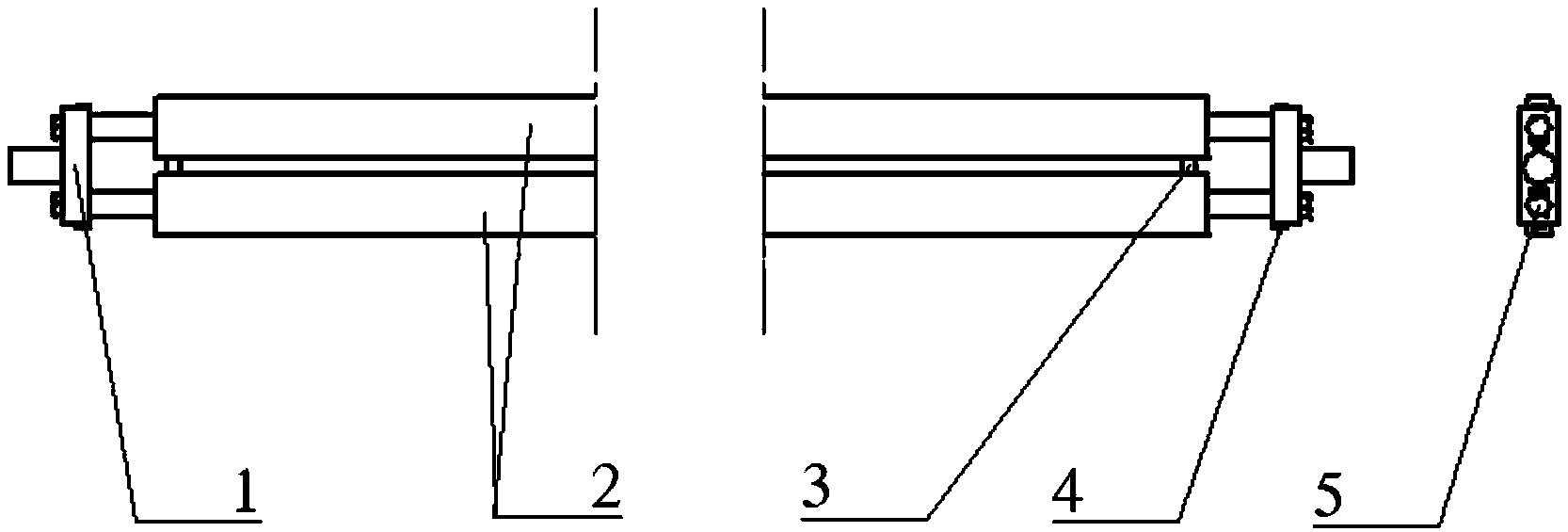
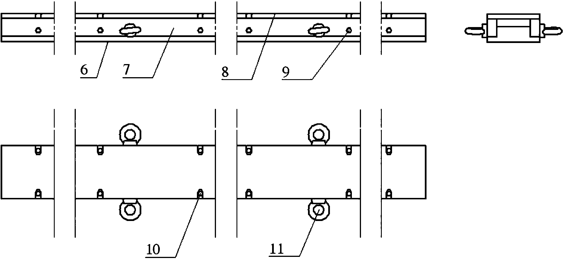
[0032] Such as figure 1 As shown, a method for forming a rectangular reinforced pipe of carbon fiber composite material. The cross section of the rectangular reinforced pipe to be formed is a "day"-shaped structure; a rib in the middle divides the inner cavity of the rectangular pipe into two rectangular hollows. Cavity, that is, the left cavity and the right cavity; the left cavity and the right cavity have the same shape; the left cavity and the right cavity both run through the length direction of the pipe fitting; the product wall thickness is 2mm, and carbon fiber reinforced ring is used Oxygen resin prepreg tow is wound symmetrically to be quasi-isotropic. The inner cavity of the product is rounded R3, and the shape is rounded R5; the product can be divided into two parts when winding, one part is called the inner tube, the wall thickness is 1mm, and the inner tube cavity is rectangular. The inner cavity of the reinforced pipe fittings, the quantity is 2 pieces. The oth...


PUM


Abstract

The invention belongs to the technical field of forming of carbon fiber reinforced resin matrix composite structures, and relates to a forming method for a rectangular carbon fiber composite reinforced pipe fitting. The reinforcing ribs of the rectangular carbon fiber reinforced resin matrix composite reinforced pipe fitting prepared by adopting the method cannot generate distortion deformation; inner-cavity round corners and an outline round corner of the pipe fitting are relatively regular, and stress concentration points are reduced, so that the mechanical properties of products are ensured; in addition, the method is simple to operate, and the reliability in quality of the products is high. The forming method has the advantages that wound mandrels are rigid molds, winding equipment can be fully utilized, and efficiency is higher; mold-filling and demolding are simple and easy to operate, and forming pressure is stable and controllable.

Description

technical field [0001] The invention relates to a forming method of a rectangular reinforced pipe fitting of carbon fiber composite material, and belongs to the technical field of structural forming of carbon fiber reinforced resin-based composite material. Background technique [0002] Carbon fiber reinforced resin matrix composite material rod and tube structure is a typical unit of composite material components. It is a commonly used structural component in aviation and spacecraft structures. Most large satellite antenna brackets use carbon fiber reinforced resin matrix composite material pipe fittings. [0003] Carbon fiber reinforced resin matrix composite material pipes are usually formed by fiber winding, prepreg layering, pultrusion molding, heat shrinkage molding and other processes. There are two forms, one is external pressurization and the other is internal pressurization. The shape of the composite square tube with external pressure has no rounded corners, and ...

Claims


Application Information

Patent Timeline
IPC IPC(8): B29C70/34
Inventor 董丰路陈维强陶积柏
Owner BEIJING SATELLITE MFG FACTORY
Learn More