Stepping type hoisting platform
A step-by-step, lifting platform technology, applied in the direction of lifting frame, lifting device, etc., can solve the problems of insufficient lifting height and low lifting efficiency, and achieve the effect of improving safety, high safety and small swing angle.
- Summary
- Abstract
- Description
- Claims
- Application Information
AI Technical Summary
Problems solved by technology
Method used
Image
Examples
Embodiment 1
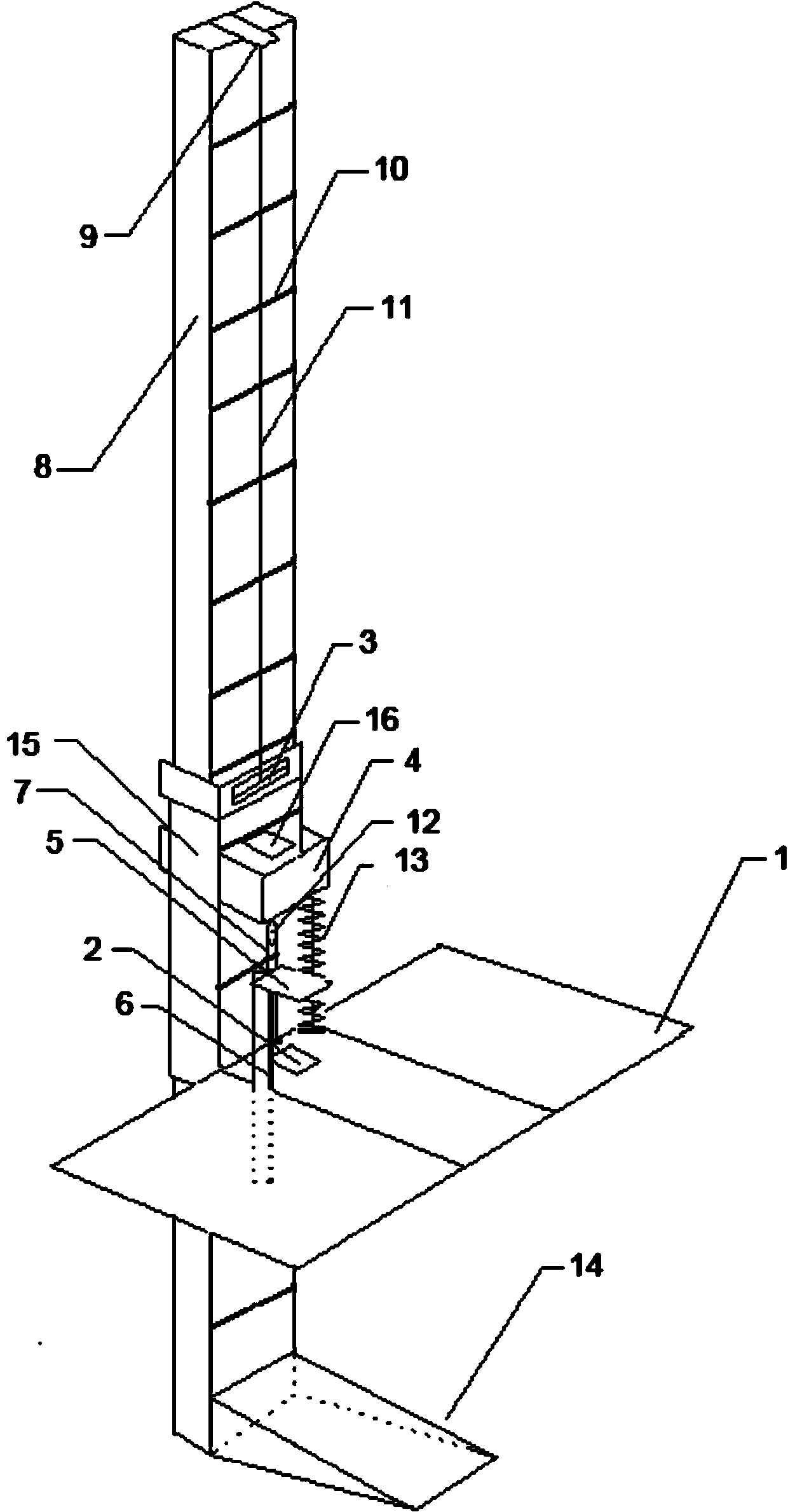
[0042] Such as figure 1 As shown, the stepping lift platform includes a working surface 1, a first positioning lock 2, a shift bracket 4, a pedal 5, a pedal bracket 6, a steel cable 7, a supporting frame 8, a steel cable joint 9, a crosspiece 10, and a pulley 12 , back-moving spring 13 table support 15 and the second positioning lock 16, several crosspieces 10 are arranged on the support frame 8, the table support is set on the support frame, the shift support 4 is installed in the table support 15, and is set on the support frame 8 Above, the worktable 1 is fixedly connected with the support of the tabletop, and the first positioning lock 2 is arranged on the worktable 1, and the lock head of the first positioning lock 2 is matched with the crosspiece, and the first positioning lock 2 is used to flexibly connect the worktable 1 and the The support frame, the shift bracket is arranged above the worktable 1, the shift bracket 4 is provided with a second positioning lock 16, the...
Embodiment 2
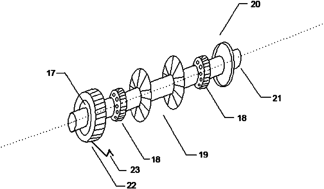
[0053] Such as figure 2 As shown, the stepping lifting platform also includes a deceleration device 3, a steel wire rope 11 and a cable joint 9, the deceleration device 3 is fixed on the table support 15, the top of the support frame 8 is provided with a steel cable joint 9, and one end of the steel wire rope 11 is fixed On the cable joint 9, the other end is connected to the deceleration device 3. The deceleration device 3 is composed of a flywheel 17, a bearing 18, a winch 19, a pulley 20, a deceleration shaft 21, a hand handle 23 and a deceleration belt 22, and is fixed on the cable joint 9. The wire rope 11 on the top is connected with the capstan 19, and the speed reduction shaft 21 is provided with a flywheel 17, a bearing 18, a capstan 19 and a belt pulley 20. The flywheel 17 makes the shaft only rotate in a single direction, and the speed reduction belt 22 is connected with the flywheel 17. The speed reduction belt 22 is provided with hand handle 23 outside, is used f...
Embodiment 3
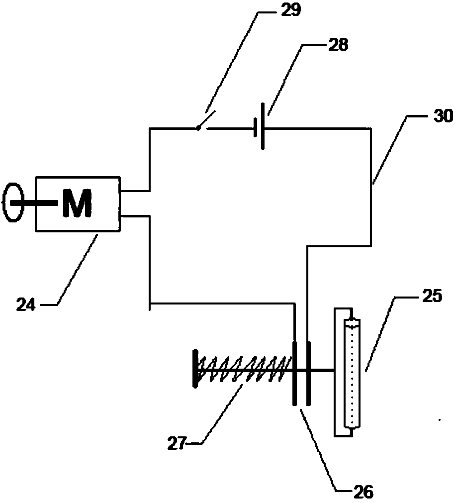
[0055] Such as image 3 Shown, winch 19 is controlled winch motor operation by winch control circuit, and winch control circuit comprises winch motor 24, pressure rope contact 25, contact piece 26, spring 27, power supply 28, switch 29 and lead wire 30, when the work table rises, The wire rope fixed in the winch 19 will become slack, and the pressure rope contact 25 stretches out under the active force of the spring 27 to close the contact piece 26. One end of the contact piece is connected to the positive pole of the power supply 28, and the other end is connected in series with the winch motor 24 and A closed circuit is formed from the switch 29 to the negative pole of the power supply 28 .
PUM
 Abstract
Description
Claims
Application Information
 - R&D
- Intellectual Property
- Life Sciences
- Materials
- Tech Scout
- Unparalleled Data Quality
- Higher Quality Content
- 60% Fewer Hallucinations
Browse by: Latest US Patents, China's latest patents, Technical Efficacy Thesaurus, Application Domain, Technology Topic, Popular Technical Reports.
© 2025 PatSnap. All rights reserved.Legal|Privacy policy|Modern Slavery Act Transparency Statement|Sitemap|About US| Contact US: help@patsnap.com


