Method for constructing water proof structure and constructing underground construction in water proof mode

An underground engineering and water isolation technology, which is applied in underground chambers, mining equipment, earthwork drilling and mining, etc., can solve the problems of poor water isolation effect of water isolation structures, poor water isolation effect, slow progress, etc.

Active Publication Date: 2013-12-11
BEIJING RAIL & TRANSIT DESIGN & RES INST
View PDF9 Cites 8 Cited by
  • Summary
  • Abstract
  • Description
  • Claims
  • Application Information

AI Technical Summary

Problems solved by technology

However, when the improved pipe curtain method is used for construction in larger-diameter steel pipes, construction operations such as cutting and welding are often performed on each steel pipe, making the construction more difficult and the progress slower; moreover, the improved pipe curtain method However, the method has not made improvements in the construction of water isolation, so that the water isolation effect of the water isolation structure is still not good, and formation precipitation is still required
[0006] In summary, the pipe curtain method or the improved pipe curtain method in the prior art has the problem of poor water isolation effect when constructing underground works. Therefore, it is necessary to provide a better water isolation effect. The construction method of the water-proof structure, and the method of constructing the underground engineering by using the water-proof method, so that the water-proof structure built has a better water-proof effect, and can be carried out in an anhydrous space without stratum precipitation. Construction of underground works

Method used


Image

  • Method for constructing water proof structure and constructing underground construction in water proof mode
  • Method for constructing water proof structure and constructing underground construction in water proof mode
  • Method for constructing water proof structure and constructing underground construction in water proof mode

Examples


Embodiment Construction

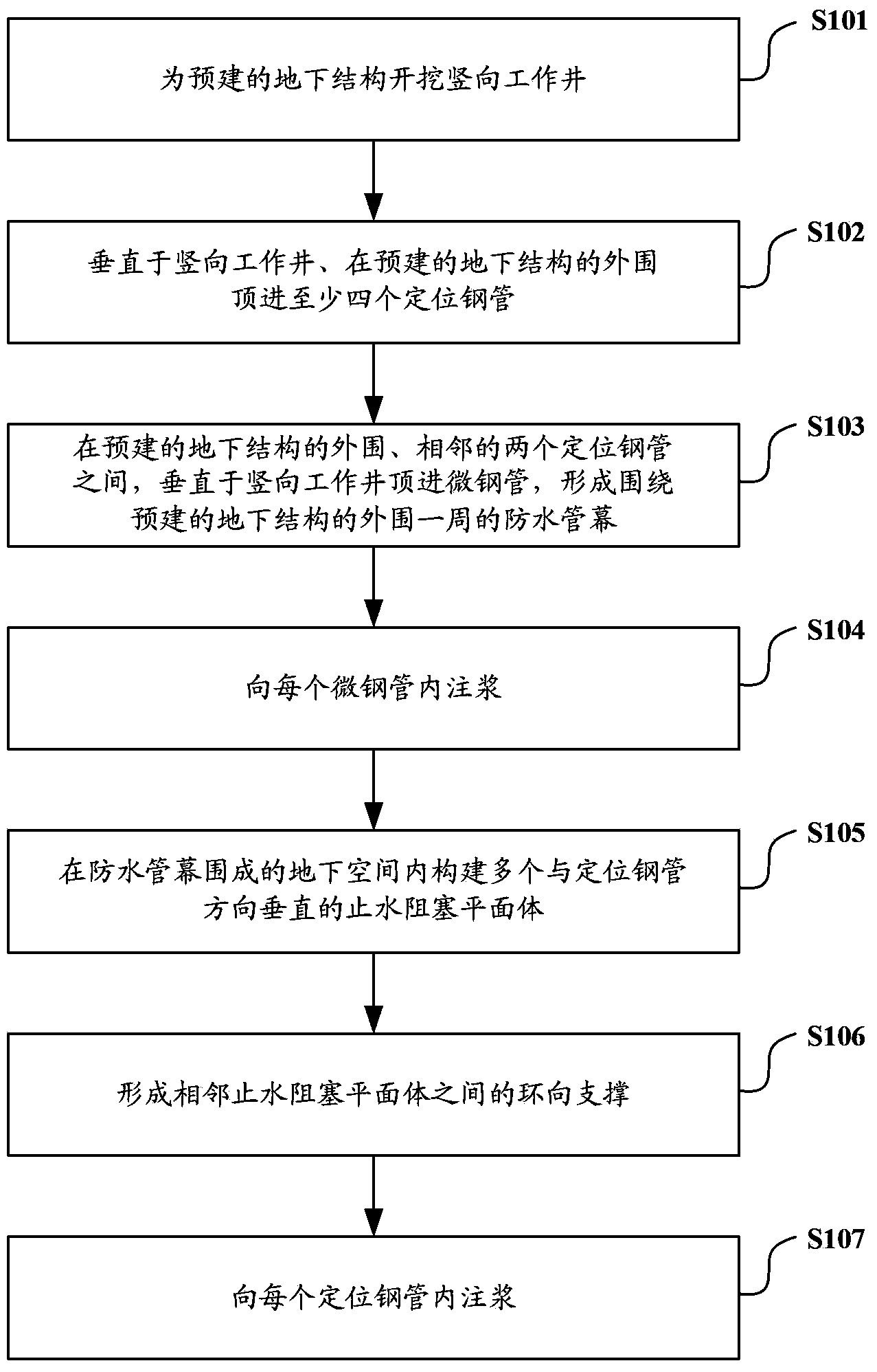
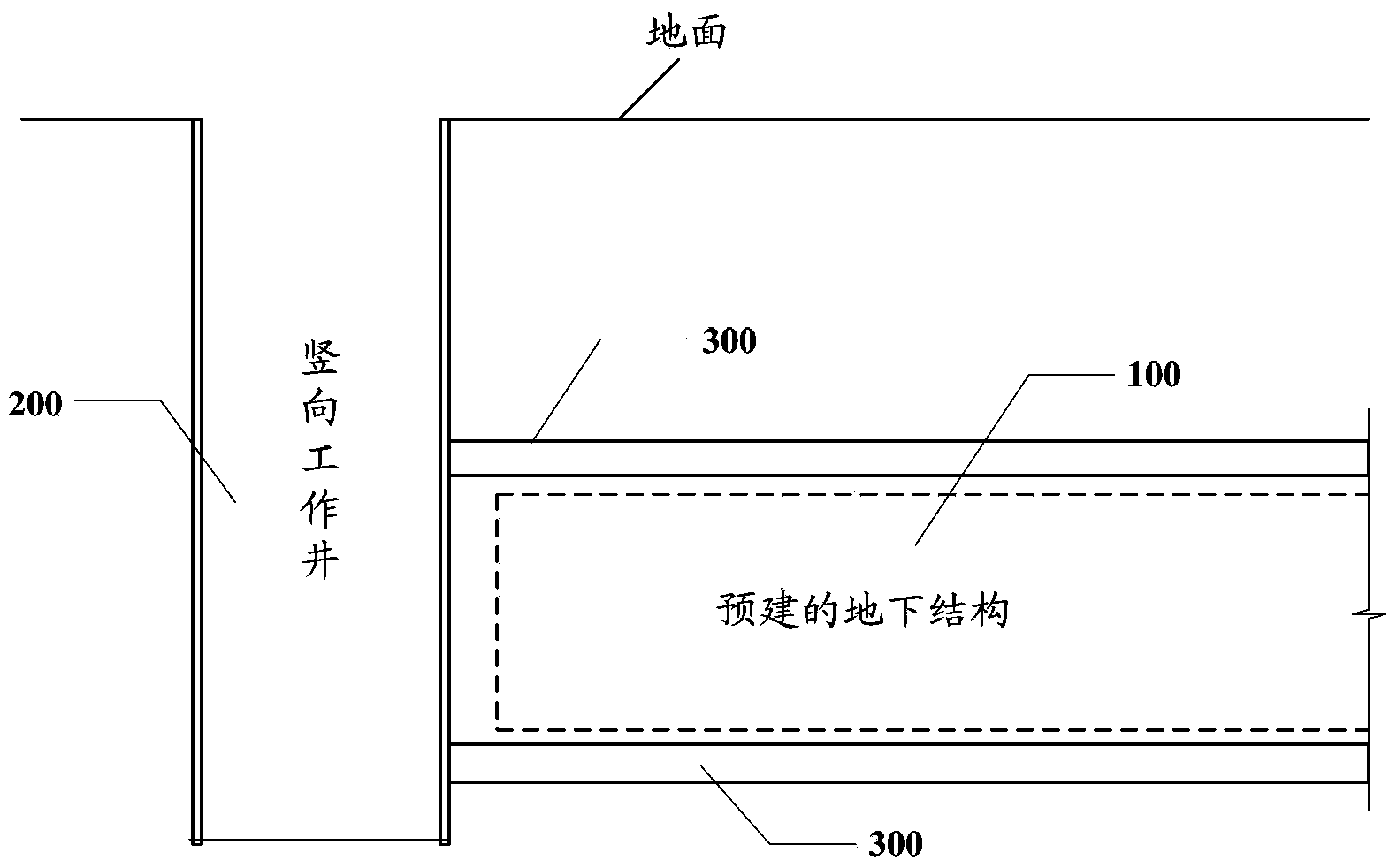
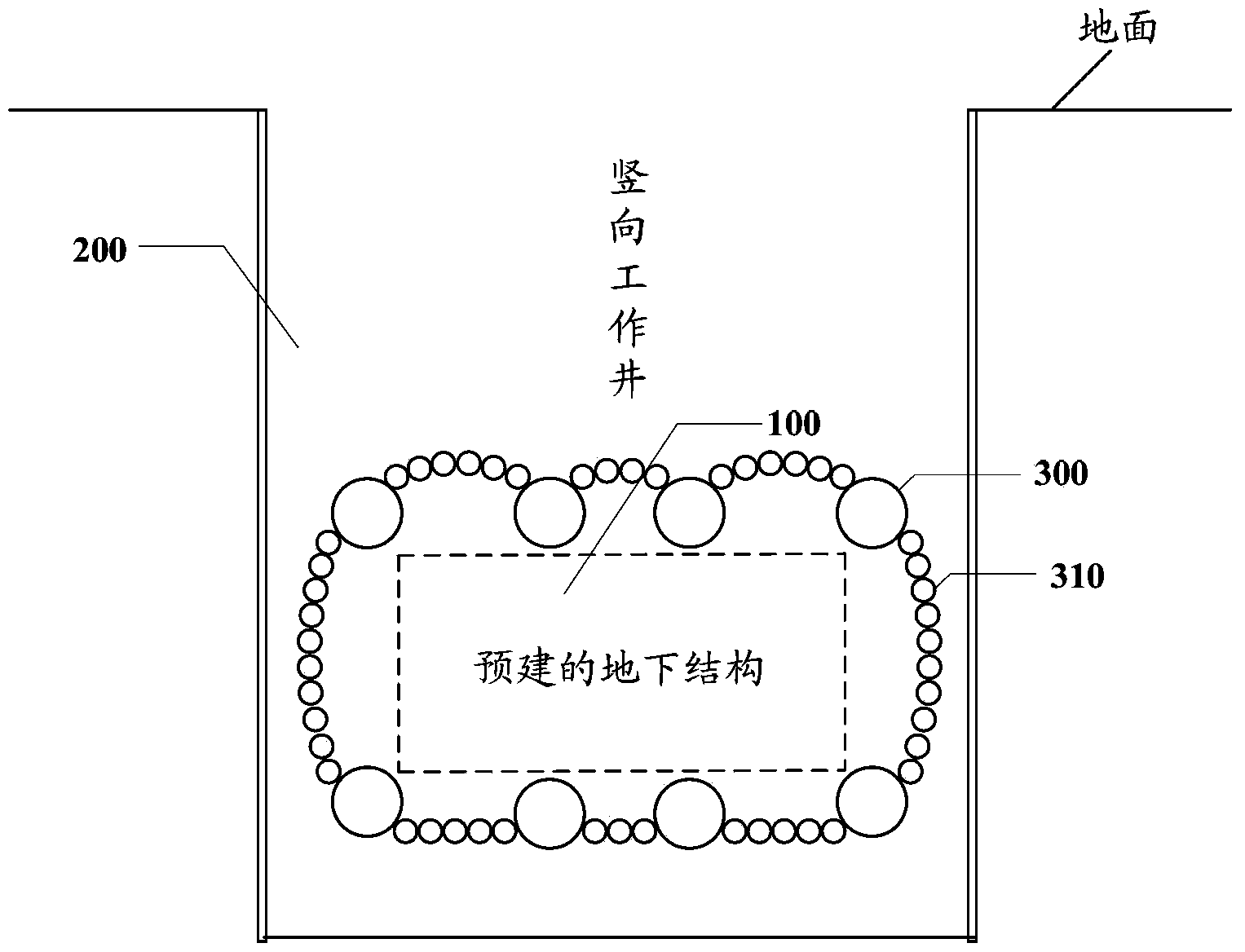
[0072] In order to make the object, technical solution and advantages of the present invention clearer, the present invention will be described in further detail below with reference to the accompanying drawings and preferred embodiments. However, it should be noted that many of the details listed in the specification are only for readers to have a thorough understanding of one or more aspects of the present invention, and these aspects of the present invention can be implemented even without these specific details.

[0073] The main idea of ​​the present invention is that when constructing the water-resistant structure, in the pre-excavated vertical shaft, the positioning steel pipes and micro-steel pipes are laid out in a non-excavation manner to form a water-riser curtain around the periphery of the pre-built underground project; And pre-set a number of grouting holes on the wall of the micro-steel pipe, the soil around the lock can be grouted through the grouting holes, so ...


PUM


Abstract

The invention discloses a method for constructing a water proof structure and constructing underground construction in a water proof mode. The method for constructing the water proof structure includes the steps that positioning steel tubes are laid on the outer periphery of prebuilt underground construction in the direction perpendicular to the extending direction of a vertical shaft after the vertical shaft is excavated for the prebuilt underground construction; micro steel tubes are jacked into the space between adjacent positioning steel tubes on the outer periphery of the prebuilt underground construction in the direction perpendicular to the extending direction of the vertical shaft; the adjacent positioning steel tubes and the micro steel tubes are connected through fore shafts and adjacent micro steel tubes are connected though fore shafts to form a water proof tube curtain encircling the outer periphery of the prebuilt underground construction; grout is injected into the micro steel tubes; water stop blocking plane bodies perpendicular to the positioning steel tubes and away from the vertical shaft at different distances are constructed in the underground space defined by the water proof tube curtain; annular supporting bodies parallel to the water stop blocking plane bodies are formed between adjacent water stop blocking plane bodies along the inner side wall of the water proof tube curtain. The water proof structure constructed through the method has the good water proof effect, and enables the water proof tube curtain to have strong rigidity.

Description

technical field [0001] The invention relates to the technical field of underground engineering, in particular to a method for constructing a water-proof structure and adopting a water-proof method for constructing an underground project. Background technique [0002] At present, there are more and more constructions of underground projects such as underground crossing passages, underground traffic tunnels, underground pipeline tunnels and subway stations. When carrying out these underground engineering constructions, the methods usually adopted include open-cut method and underground method. The open cut method is simple and fast in construction, but it has a great damage or impact on the surrounding environment, and it is only suitable for construction under the condition of shallow buried depth. During the construction of the underground excavation method, the ground of the pre-built underground engineering part is not fully excavated, which has little impact on the surro...

Claims


Application Information

Patent Timeline
Patent Type & Authority Applications(China)
IPC IPC(8): E21D11/38
Inventor 罗富荣郝志宏万学红杨秀仁张继菁苏立勇冯爱军雷崇红李松梅张丽何海健冯欣李培
Owner BEIJING RAIL & TRANSIT DESIGN & RES INST
Why Eureka
Try Eureka