Borehole profile rock and soil mass layered deformation optical fiber measuring method

A technology of optical fiber measurement and rock and soil mass, which is applied in the direction of measuring devices, optical devices, instruments, etc., to achieve the effect of overcoming moisture and precise positioning

Inactive Publication Date: 2013-12-11
NANJING UNIV +2
View PDF3 Cites 24 Cited by
  • Summary
  • Abstract
  • Description
  • Claims
  • Application Information

AI Technical Summary

Problems solved by technology

[0005] The purpose of the present invention is: in order to overcome the deficiencies of the existing conventional monitoring methods and means for rock-soil layered deformation, to propose a method for measuring the layered deformation of rock-soil body with an optical fiber in the borehole section

Method used


Image

  • Borehole profile rock and soil mass layered deformation optical fiber measuring method
  • Borehole profile rock and soil mass layered deformation optical fiber measuring method

Examples


Embodiment Construction

[0018] The present invention will be further described below in conjunction with the accompanying drawings.

[0019] as attached figure 1 Shown, basic method of the present invention is as follows:

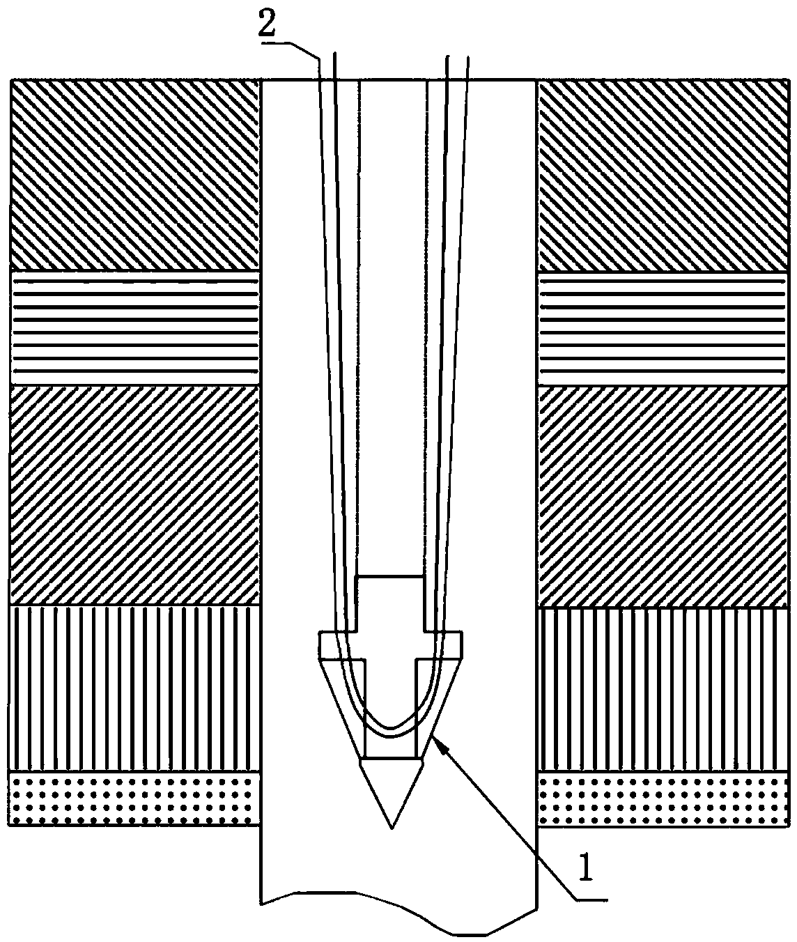
[0020] Step 1 is to drill a hole to form a hole: first, select a measurement point, and use a drilling rig to perform full core drilling to form a certain depth of hole. The depth of the drill hole can reach hundreds of meters according to specific needs; The soil layer is cataloged, and the catalog is used to better grasp the test results of different soil layers during observation; figure 1 In , different patterns are used to represent the soil layers with different textures on both sides of the borehole;

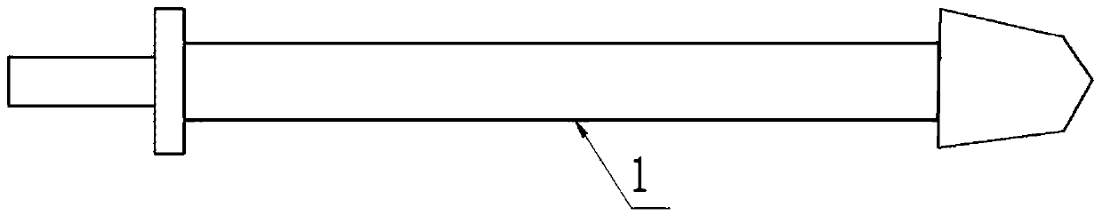
[0021] Step 2 is to place the optical cable: after the hole is formed, the diameter of the drilled hole is 130-200mm, and the distributed sensing optical fiber 2 with the counterweight guide hammer 1 is sent into the hole with a drill pipe, and two optical fibers are arrang...


PUM


Abstract

The invention discloses a borehole profile rock and soil mass layered deformation optical fiber measuring method. A measurement point is selected, and a soil layer is cataloged after being bored. When a hole is formed, a sensing optical fiber is laid and then the hole is backfilled. When the rock and soil mass around the sensing optical fiber deforms, the sensing optical fiber is driven to be deformed due to wrapping force of surrounding soil mass. Strain distribution of the sensing optical fiber is measured via BOTDR/A and other technologies so that strain distribution state of corresponding positions of a borehole profile is obtained. Integration of the corresponding positions is performed on the obtained strain along the optical fiber so that deformation state of each soil layer in deep rock and soil mass can be obtained. Therefore, distributed type measurement of borehole profile rock and soil mass layered deformation is realized. The method is applicable to the field of rock and soil mass deformation monitoring, such as ground subsidence, ground collapse, mines, etc.

Description

technical field [0001] The invention relates to a deformation measurement method of rock and soil, in particular to an optical fiber measurement method for layered deformation of rock and soil in a drilling section. Background technique [0002] The exploitation of underground resources often easily causes deformation of rock and soil mass, causing disasters such as uneven ground settlement and ground subsidence. Especially in the roadways and goafs formed by coal mining, the force of the surrounding rock and soil changes, causing problems such as soil deformation and roof shedding. In view of the above problems, the use of borehole observation channels to measure the deformation of rock and soil in each layer is one of the main methods currently used. Therefore, it is particularly important to choose an effective method for measuring the deformation of rock and soil in the borehole section. [0003] Among the existing soil deformation measurement technologies, the large-s...

Claims


Application Information

Patent Timeline
Patent Type & Authority Applications(China)
IPC IPC(8): G01B11/16
Inventor 施斌魏广庆朴春德童恒金卢毅席均孙义杰刘瑾
Owner NANJING UNIV
Why Eureka
Try Eureka