Sagger crack detection base platform

A crack detection and abutment technology, applied in the direction of optical testing flaws/defects, etc., can solve the problems of no unified damage judgment standard, large radiation detection, high labor intensity, etc., to ensure accuracy, ensure comprehensiveness, and reduce labor. the effect of strength

Active Publication Date: 2013-12-11
HENGLI ELETEK
View PDF7 Cites 10 Cited by
  • Summary
  • Abstract
  • Description
  • Claims
  • Application Information

AI Technical Summary

Problems solved by technology

[0002] At present, manual detection is mostly used for crack detection in saggers. Manual detection is not only labor-intensive, but also has no uniform damage judgment standard.
However, the existing automatic damage detection mostly uses ray detection and air pressure detection. The radiation detection of ray detection is large and the cost is high; the air pressure detection is only for empty bowls, and it is easy to cause damage to the sagger during the inflation process.

Method used


Image

  • Sagger crack detection base platform

Examples


Embodiment Construction

[0020] The present invention will be further described below in conjunction with accompanying drawing:

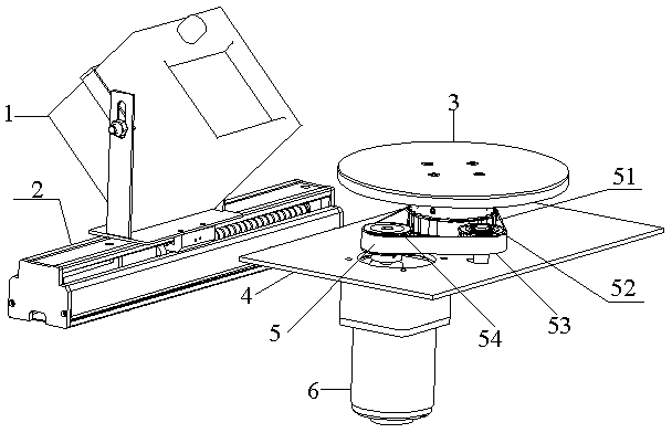
[0021] Such as figure 1 The shown sagger crack detection base includes a rotating device for rotating the object to be tested and an image acquisition device located on one side of the rotating device. There is a photoelectric sensor on the production line, which can judge whether the sagger enters the detection range, so as to ensure the accuracy of image collection.

[0022] Further, the rotating device includes a rotating motor 6, a synchronous belt transmission mechanism 5 connected to the power output end of the rotating motor, and a rotating disk 3 fixed on the synchronous belt transmission mechanism. Preferably, the rotating motor 6 is a servo motor. Specifically, by setting the rotation angle of the servo motor 6, it drives the synchronous transmission mechanism 5 to work, so that the rotating disk 3 on which the sagger to be tested is placed rotates 90° sequentia...


PUM


Abstract

The invention relates to a sagger crack detection base platform which comprises a rotating device for rotating an object to be detected and an image acquisition device positioned on one side of the rotating device, wherein the rotating device comprises a rotating motor, a synchronous belt transmission mechanism connected with the power output end of the rotating motor and a rotating disk fixedly arranged on the synchronous belt transmission mechanism; the image acquisition device comprises a moving module and a camera; the rotating motor is a servo motor; the synchronous belt transmission mechanism comprises a driving wheel fixedly arranged on a rotating shaft of the rotating motor, driven wheels movably connected with a rotating shaft of a supporting plate and a transmission belt meshed with the driving wheel and the driven wheels; the driven wheels comprise a driven wheel for rotating the rotating disk and a driven wheel for tensioning the transmission belt. When a sagger rotates automatically and sequentially, the image acquisition and processing device is used for detecting every single surface of the sagger. The sagger crack detection base platform has the characteristics of lossless non-contact automatic detection, short detection period, low cost and the like.

Description

technical field [0001] The invention relates to a non-destructive testing device, in particular to a sagger crack detection base. Background technique [0002] At present, manual detection is mostly used for crack detection in saggers. Manual detection is not only labor-intensive, but also has no uniform damage judgment standard. However, the existing automatic damage detection mostly adopts ray detection and air pressure detection. Radiation detection has large radiation and high cost; air pressure detection is only for empty bowls, and the sagger is easy to be damaged during the inflation process. Contents of the invention [0003] The object of the present invention is to provide a sagger crack detection base, which can rotate the sagger in turn and use an image acquisition and processing device to detect each single side of it, with non-destructive non-contact automatic detection and short detection cycle and low cost features. [0004] In order to achieve the above ...

Claims


Application Information

Patent Timeline
Patent Type & Authority Applications(China)
IPC IPC(8): G01N21/88
Inventor 叶志奚思孙康
Owner HENGLI ELETEK
Why Eureka
Try Eureka