
Pulse laser ranging high-low threshold value leading-edge discriminator circuit and discrimination method thereof

A pulsed laser ranging, high and low threshold technology, applied in measurement devices, electromagnetic wave re-radiation, radio wave measurement systems, etc., can solve the problems of increasing system volume, precision defects, low precision, etc. Improve and ensure the effect of accuracy

Active Publication Date: 2013-12-11
江苏深锐智能科技有限公司
View PDF3 Cites 8 Cited by
  • Summary
  • Abstract
  • Description
  • Claims
  • Application Information

AI Technical Summary

Problems solved by technology

These two methods have their own advantages and disadvantages. Frontier identification technology is simple in circuit and easy to implement, but the precision is not high; while constant ratio timing technology has high precision, but it will make the circuit complicated due to the need to use high-precision analog delay lines. , while increasing the volume of the entire system
Compared with the constant ratio timing technology, the frontier identification technology is easier to implement, and it is more suitable for small laser range finders, but because of its own accuracy defects, it is necessary to improve and innovate it

Method used


Image

  • Pulse laser ranging high-low threshold value leading-edge discriminator circuit and discrimination method thereof

Examples


Embodiment Construction

[0017] The present invention is described in further detail below in conjunction with accompanying drawing:

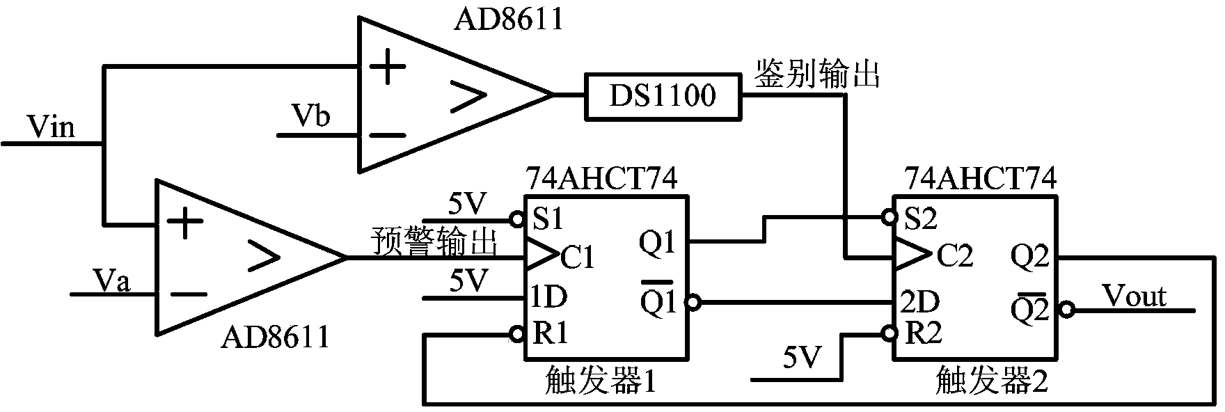
[0018] see figure 1 , the pulse laser ranging high and low threshold frontier discrimination circuit of the present invention, the circuit includes two comparators AD8611, active delay line DS1100, a first flip-flop 1 and a second flip-flop 2. Firstly, connect the voltage pulse signal obtained by the detector to the positive input terminals of two comparators AD8611 through wires, and the negative input terminals of the two comparators AD8611 are connected to two different voltages: voltage Va and voltage Vb; Among them, the voltage Va is greater than the voltage Vb; the comparator AD8611 with the voltage Vb as the negative input connects an active delay line DS1100 with a wire at the output end as a discrimination output; the output terminal of the comparator AD8611 with the voltage Va as the negative input directly serves as an early warning Output; the early warnin...


PUM


Abstract

The invention discloses a pulse laser ranging high-low threshold value leading-edge discriminator circuit and a discrimination method of the pulse laser ranging high-low threshold value leading-edge discriminator circuit. The pulse laser ranging high-low threshold value leading-edge discriminator circuit comprises two comparators AD8611, an active delay line DS1100, a first trigger and a second trigger. TTL output serves as output of the comparators AD8611 used by the pulse laser ranging high-low threshold value leading-edge discriminator circuit, the propagation delay is 4 nanoseconds, and the rise time of an output waveform is 3 nanoseconds. Meanwhile, due to the fact that the two high-speed D triggers are used for carrying out shaping and shake removal on the output of the comparators AD8611, a high-quality signal can be obtained to carry out time measurement. Meanwhile, due to the facts that the active delay line DS1100 is further used, and the active delay line DS1100 is small in packaging size and high in accuracy, the task of adjusting the time sequence can be accomplished on the situation that accuracy and the size of a system are ensured. According to the pulse laser ranging high-low threshold value leading-edge discriminator circuit, the existing leading-edge discrimination technology is improved, and the pulse laser ranging high-low threshold value leading-edge discriminator circuit has the advantages of being high in accuracy and simple in structure, is a circuit which is high in ranging accuracy, and is applicable to a laser ranging circuit, wherein a pulse rising edge of a pulse laser in the laser ranging circuit is dozens of nanoseconds.

Description

technical field [0001] The invention belongs to the technical field of pulse laser ranging, and relates to a discrimination circuit, in particular to a pulse laser ranging high and low threshold leading edge discrimination circuit. Background technique [0002] In order to eliminate the time wander caused by the amplitude effect of the laser echo pulse signal and the time jitter caused by the noise, and ensure the ranging accuracy, the existing laser range finder generally adopts different time identification techniques. There are two kinds of time identification technologies that are used more now, one is frontier identification technology, and the other is called constant ratio timing technology. These two methods have their own advantages and disadvantages. Frontier identification technology is simple in circuit and easy to implement, but the precision is not high; while constant ratio timing technology has high precision, but it will make the circuit complicated due to t...

Claims


Application Information

Patent Timeline
Patent Type & Authority Applications(China)
IPC IPC(8): G01S7/48G01S17/08
Inventor 孙剑张潮田征郭希良杨鹏飞
Owner 江苏深锐智能科技有限公司
Learn More