Broadband wire source for planar waveguide CTS antenna feed device

A technology of antenna feeding and planar waveguide, which is applied to antennas, waveguide horns, circuits, etc., can solve the problem that the ideal broadband line source with equal amplitude and phase cannot be realized, and achieves simple structure, convenient later use and maintenance, and improved caliber efficiency effect

Inactive Publication Date: 2013-12-11
XIDIAN UNIV
View PDF4 Cites 23 Cited by
  • Summary
  • Abstract
  • Description
  • Claims
  • Application Information

AI Technical Summary

Problems solved by technology

[0009] The purpose of the embodiment of the present invention is to provide a broadband line source for the feeding device of the planar waveguide CTS antenna, which aims to solve the problem of generating an ideal broadband line source with equal amplitude and phase in the actual project existing in the existing waveguide CTS antenna. Problems that cannot be achieved in

Method used


Image

  • Broadband wire source for planar waveguide CTS antenna feed device
  • Broadband wire source for planar waveguide CTS antenna feed device
  • Broadband wire source for planar waveguide CTS antenna feed device

Examples


Embodiment Construction

[0035] In order to make the object, technical solution and advantages of the present invention more clear, the present invention will be further described in detail below in conjunction with the examples. It should be understood that the specific embodiments described here are only used to explain the present invention, not to limit the present invention.

[0036] The application principle of the present invention will be further described below in conjunction with the accompanying drawings and specific embodiments.

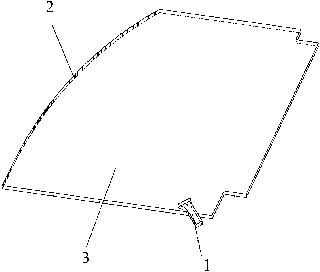
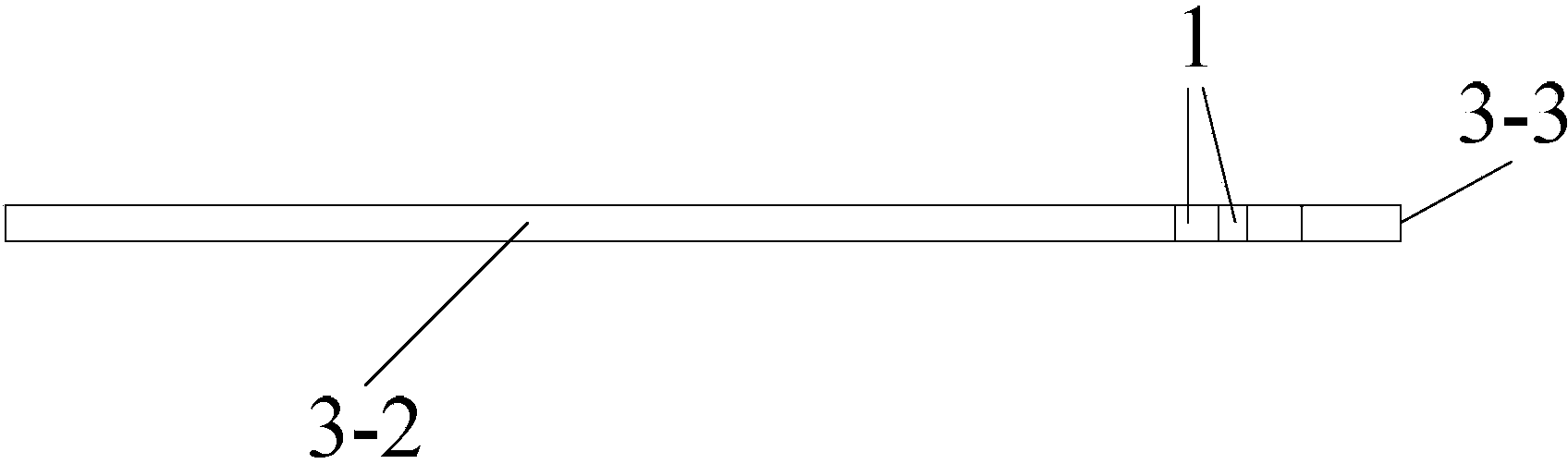
[0037] Such as figure 1 As shown, the broadband line source used for the planar waveguide CTS antenna feeder of the embodiment of the present invention is mainly made up of H-plane fan-shaped horn antenna 1, offset parabolic reflector 2 and planar waveguide 3; H-plane fan-shaped horn antenna 1 and The offset parabolic reflector 2 is arranged inside the planar waveguide 3. By adjusting the position of the H-plane fan-shaped horn antenna 1 so that its phase center...


PUM


Abstract

The invention discloses a broadband wire source for a planar waveguide CTS antenna feed device. The broadband wire source comprises an H-plane sectorial horn antenna, a bias parabolic reflection plane and a flat waveguide. The H-plane sectorial horn antenna and the bias parabolic reflection plane are arranged inside the flat waveguide, and the phase center of the H-plane sectorial horn antenna is arranged at the focus of the bias parabolic reflection plane. According to the invention, cylindrical waves are converted into plane waves, the plane waves are generated by using a reflector antenna principle, and the horn antenna is arranged at the focus of a paraboloid reflector so that a horn antenna radiation field passes through the reflector and generates the plane wave with equal amplitude and the same phase at the caliber surface of the reflector. The working frequency band is wide; the feed source shielding is eliminated and the caliber efficiency is enhanced through a bias; the structure is enclosed so that the edge diffraction effects of a conventional bias paraboloid are removed; and the structure is simple so that adjusting and assembling are easy, late use and maintenance are convenient, and the problem can be solved that the ideal wire source with equal amplitude and the same phase, generated by a conventional waveguide CTS antenna, cannot be realized in an actual project.

Description

technical field [0001] The invention belongs to the technical field of antennas and feed sources, and in particular relates to a broadband line source used for a planar waveguide CTS antenna feed device. Background technique [0002] At present, the electronically scanned antenna is facing great challenges, especially its high cost input in the military and commercial markets, and the realization of a high-efficiency, low-cost planar electronically scanned antenna in the X-band is a very difficult task, and, In the military and commercial markets, the high sensitivity and multi-purpose characteristics and functions of the electronically scanned antenna with low profile radiation aperture are also very important. Therefore, a low-cost electronically scanned antenna that can be used in the military and commercial fields is proposed Technology is a mission-critical, desired characteristics include: high efficiency; high gain; light weight, low mechanical profile; high-precision...

Claims


Application Information

Patent Timeline
Patent Type & Authority Applications(China)
IPC IPC(8): H01Q13/02H01Q19/12
Inventor 张鹏飞董海林龚书喜徐云学刘英姜文王夫蔚
Owner XIDIAN UNIV
Why Eureka
Try Eureka