Signal monitoring and optimizing method and system

A technology of signal monitoring and optimization method, applied in the field of mobile communication, can solve the problems of different levels of carrier frequency noise floor, unable to locate and solve in time, unable to distinguish between same-frequency interference signals, etc.

Active Publication Date: 2013-12-11
ULTRAPOWER SOFTWARE
View PDF6 Cites 3 Cited by
  • Summary
  • Abstract
  • Description
  • Claims
  • Application Information

AI Technical Summary

Problems solved by technology

[0003] However, the traditional frequency scanner can only measure the wireless signal coverage status of the BCCH frequency point, that is, the receiving level and C/I measurement of the BCCH frequency point can be measured, and at the same time, the GPS position information and measurement time information can be obtained. The traditional frequency scanning technology cannot Effectively test the parameters related to TCH frequency points other than BCCH frequency points. In the prior art, the frequency sweep test of BCCH frequency points is usually used to perform approximate equivalent analysis on the TCH frequency points of the same cell. Specifically:
[0004] 1. The traditional frequency scanner can only measure the level of the BCCH frequency point, and cannot measure the receiving level, noise floor and C/I of all carrier frequencies including the TCH frequency point
[0005] 2. The traditional frequency scanner can only measure and decode the BCCH channel. The BCCH frequency point is full-power transmission, which is different from the TCH frequency point; for the

Method used


Image

  • Signal monitoring and optimizing method and system
  • Signal monitoring and optimizing method and system
  • Signal monitoring and optimizing method and system

Examples


Embodiment Construction

[0074] In order to make the objectives, technical solutions and advantages of the present invention clearer, the embodiments of the present invention will be described in further detail below in conjunction with the accompanying drawings.

[0075] See figure 1 , The embodiment of the present invention provides a signal monitoring and optimization method, which specifically includes:

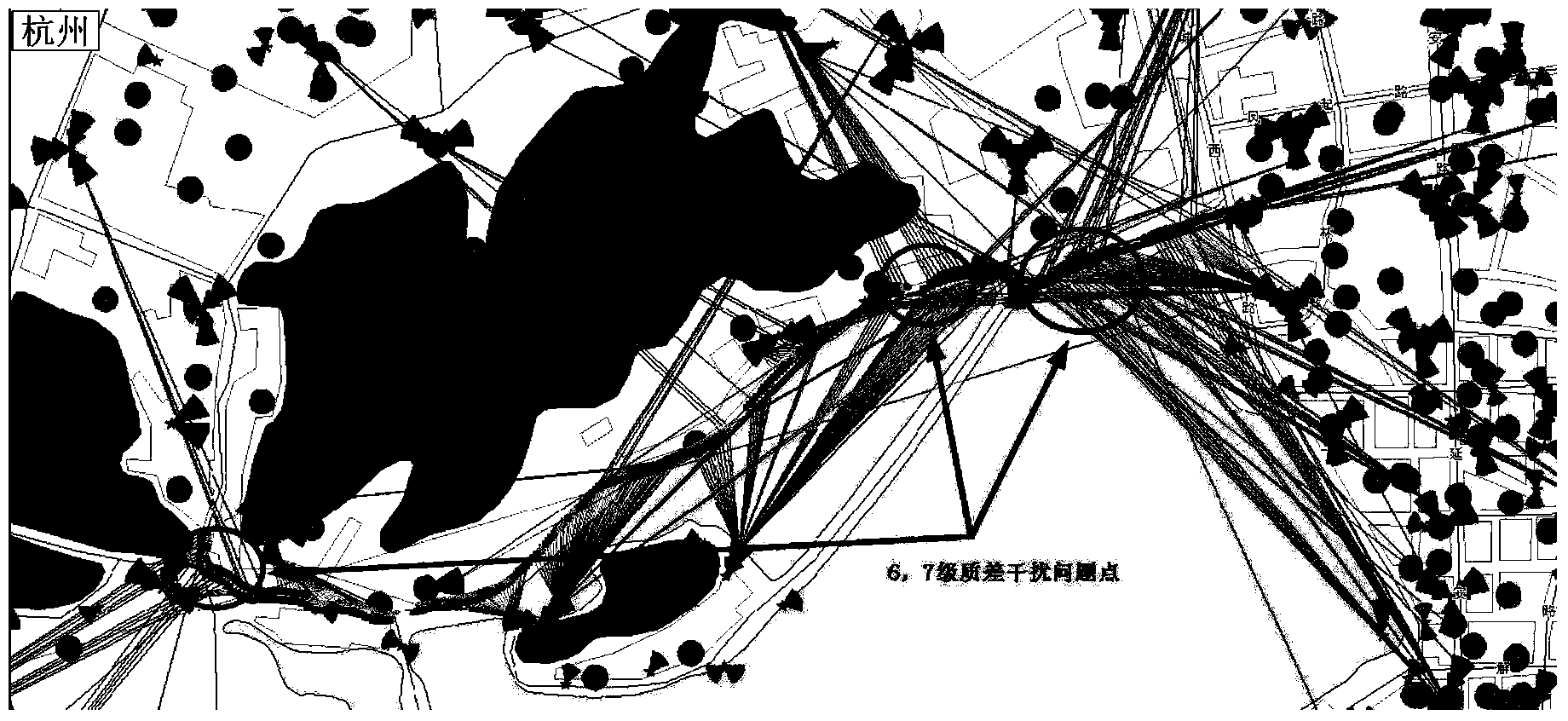
[0076] S101: Rasterize the selected test road section.

[0077] The test route is rasterized, for example, a road raster is formed in an area of ​​50 meters X 50 meters.

[0078] S102: Perform frequency sweep on each grid of the selected test road section, and record the frequency sweep data in real time.

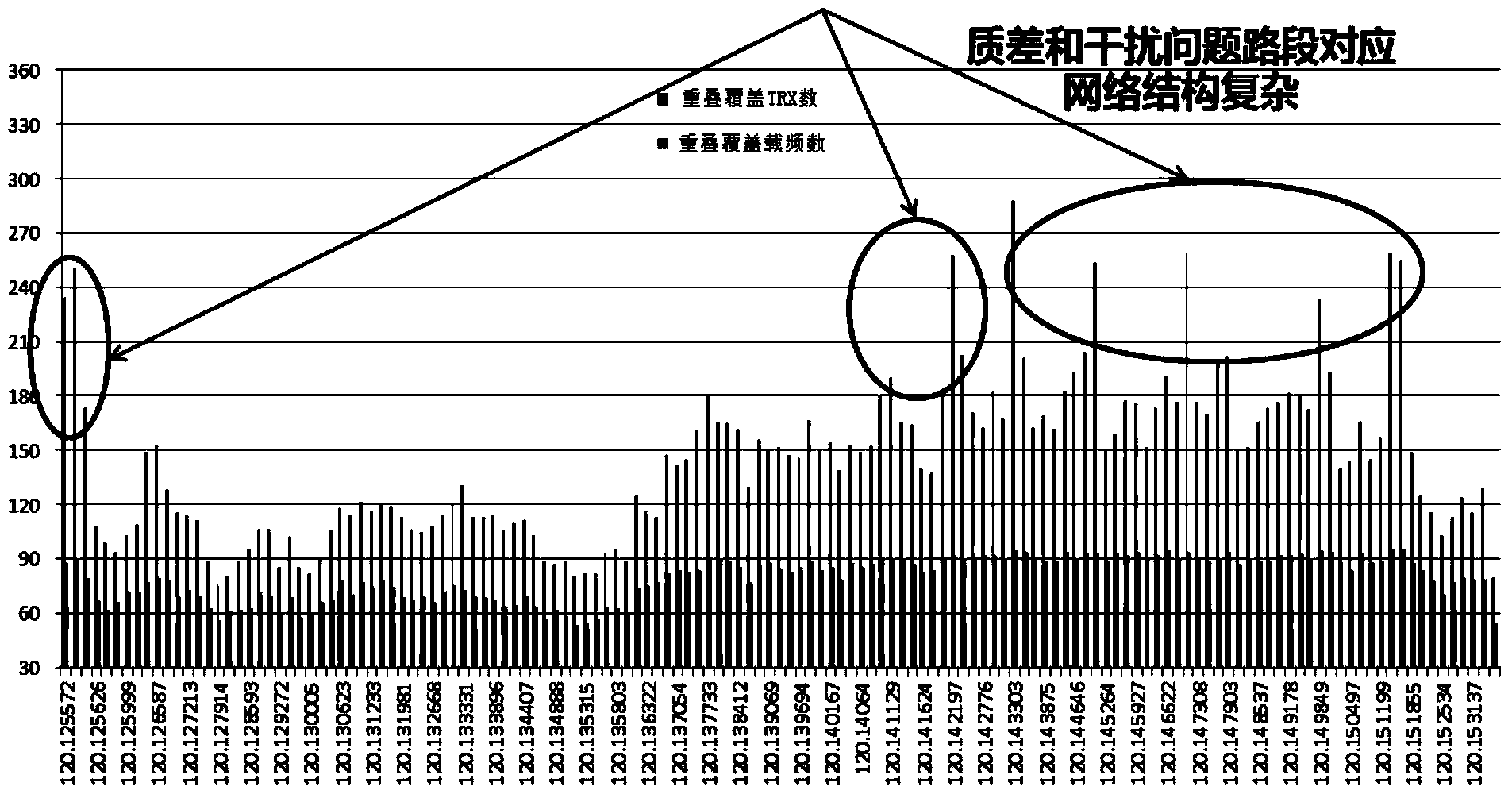
[0079] S103: Perform separately for each grid: calculate the road structure index and / or road frequency reuse density of each frequency point in the grid according to the frequency sweep data.

[0080] Specifically, calculating the road structure index and / or road frequency reuse density of each frequenc...


PUM


Abstract

The invention discloses a signal monitoring and optimizing method and system and provides a wireless network structure assessment technology based on high-precision service channel timeslot frequency sweeping. The number of road overlapping and covering frequency points, road receiving indexes and road frequency share density values are obtained through accurate calculation, the comprehensive performance of a wireless network structure can be objectively reflected, subjectivity, inaccuracy and uncertainty in equivalent TCH frequency point measuring of basic traditional BCCH frequency point frequency sweeping measurement are overcome, and therefore monitoring and managing can be accurately performed on a communication signal. In addition, warning and reasonable optimizing and adjusting are performed according to the practical conditions of the signal, and the overall performance of a honeycomb wireless network is fundamentally improved and increased. Further, the comprehensive performance of the wireless network can be objectively and accurately assessed, a key cell and a key frequency point utilizing carrier timeslot grade measuring to perform accurate positioning and cause wireless network problems provide scientific and accurate measuring and analyzing means for adjusting and optimizing the wireless network structure.

Description

Technical field [0001] The present invention relates to the field of mobile communication technology, in particular to a method and system for signal monitoring and optimization. Background technique [0002] In the prior art, a traditional frequency sweeper is usually used to measure mobile communication signals to obtain frequency sweep data, which is an important basis for evaluating and optimizing communication network conditions. The frequency sweep data measured by the traditional frequency scanner can reflect the signal coverage, and is not limited by manufacturers, equipment, and parameters; the sweep frequency test does not occupy communication system resources like business tests, and the test is simple, which is the current wireless network One of the important technical means of analysis. [0003] However, the traditional frequency scanner can only measure the wireless signal coverage of the BCCH frequency point, that is, it can measure the reception level and C / I meas...

Claims


Application Information

Patent Timeline
IPC IPC(8): H04B17/00H04W24/02
Inventor 黄剑锋
Owner ULTRAPOWER SOFTWARE
Why Eureka
Try Eureka