

Heat sink for led lighting
An LED lighting and radiator technology, applied in lighting and heating equipment, lighting devices, cooling/heating devices for lighting devices, etc., can solve problems such as inability to effectively dissipate heat, and achieve the effect of improving rigidity and reducing manufacturing costs
- Summary
- Abstract
- Description
- Claims
- Application Information
AI Technical Summary
Problems solved by technology
Method used
Image

Examples
no. 1 approach )
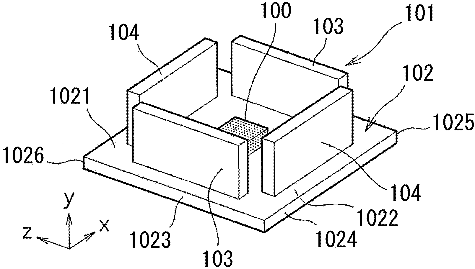
[0126] figure 1 A heat sink 101 for LED lighting according to the first embodiment is shown. This heat sink 101 for LED lighting is characterized in that, with respect to the substrate 102 on which the LED element 100 is mounted on either the front and back surfaces 1021, 1022, flat heat dissipation fins 103, 104 are integrally formed on the front surface of the substrate 102. On any one or both of the surfaces 1021, 1022 of the back, the cooling fins 103, 104 are erected outward from either the surface 1021, 1022 of the front and back of the substrate 102, and are formed at intervals from each other. Among the heat dissipation fins 103 , 104 extending in the same direction, the number of fins 103 , 104 extending in the same direction is two or less in any cross section perpendicular to either of the front and back surfaces 1021 , 1022 of the substrate 102 . Among them, the substrate 102 constitutes the mounting surface of the present invention, the heat dissipation fins 103...
no. 1 approach
[0146] figure 1 A total of four flat plate-shaped cooling fins 103 and 104 are provided on the side of the LED element mounting surface 1021 that supports the LED element 100 of the substrate 102, and the flat plate-shaped side surfaces of the cooling fins 103 and 104 are in contact with the sides of the substrate 102. The surface 1021 is provided integrally and continuously. On the other side of the back surface 1022, no heat dissipation fins are provided, and only the flat back surface 1022 exists.
[0147] In addition, the heat dissipation fins 103 and 104 provided on the side of the above-mentioned LED element mounting surface 1021 are provided symmetrically with the LED element 100 sandwiched between them, and the heat dissipation fins 103 and 103 on the left and right sides of the figure and the figure are arranged symmetrically. The upper and lower heat radiation fins 104, 104 extend in the same direction and are arranged in parallel to each other. That is, the flat ...
Embodiment
[0190] equivalent to the above figure 1 of Figure 6 , figure 2 The first modified example of Figure 47 existing examples of Figure 50 Heat sinks of various shapes in the comparative example were actually manufactured, and LED elements were assembled, and a current was applied to cause the LED elements to emit light, and then the temperature of the LED elements was measured. The results are shown in Table 1.
[0191] the above figure 2 The first modified example of Figure 47 existing examples of Figure 50 The radiators of each shape in the comparative example were manufactured from extruded rods of JIS 1100 series aluminum as raw materials by machining such as cutting. Compared to the above figure 1 of Figure 6 The heat sink of the invention example is manufactured by press forming, and the end part of the JIS 1100 series aluminum cold-rolled sheet is bent into a heat radiation fin.
[0192] In each example, the rectangular shape of the substrate is 100mm (z d...
PUM
 Abstract
Description
Claims
Application Information