Flocking structure of flocking machine

A flocking machine and flocking technology, applied in the flocking structure field of the flocking machine, can solve the problems of fluff flying in the flocking workshop, low flocking efficiency, and poor working environment in the workshop, so as to reduce the cost of fluff and the working environment. Good, ensure the effect of uniformity

Active Publication Date: 2013-12-18
WUXI QUANSHUN MACHINERY MFG
View PDF7 Cites 7 Cited by
  • Summary
  • Abstract
  • Description
  • Claims
  • Application Information

AI Technical Summary

Problems solved by technology

[0002] The flocking room of the existing flocking machine has two brush structures arranged in parallel inside, and the brush structures are set on the corresponding driving rollers. During the working process, the two driving rollers respectively drive the brush structures to make The rotation makes the fluff move from bottom to top in the middle of the two brush structures. During this process, the fluff will fly randomly from bottom to top, making the uniformity of flocking poor, and the fluff flying randomly is not easy to collect, making the flocking The material cost of fluff in the fleece process is high
[0003] The flocking room of the existing flocking machine is independently arranged at the front and rear positions of the cloth conveying pipe between the two, and the cloth conveying pipe between the two is exposed to the air. During the flocking process, due to the cloth conveying pipe Exposure to the air, which makes the floating hairs easy to float into the air, causing the fluffs to fly randomly in the flocking workshop, the working environment of the workshop is poor, and the utilization rate of the cloth delivery pipe between the two flocking rooms is low, resulting in the flocking workshop The length is long and the efficiency of flocking is low

Method used


Image

  • Flocking structure of flocking machine
  • Flocking structure of flocking machine
  • Flocking structure of flocking machine

Examples


Embodiment Construction

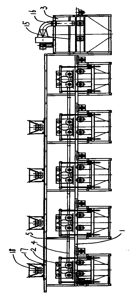
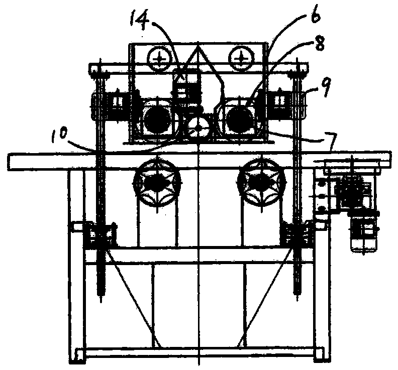
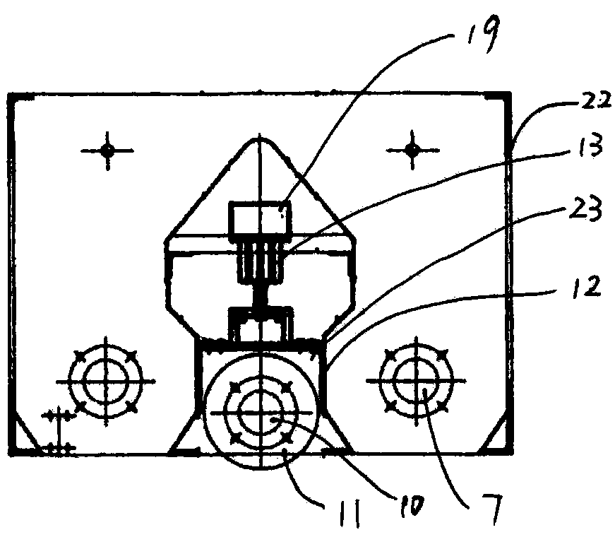
[0018] See Figure 1 ~ Figure 4 , which includes a cloth conveying pipe 1, a flocking chamber 2, and a recycling flocking chamber 3. The cloth conveying pipe 1 is evenly distributed with flocking chambers 2, and the rear of the last flocking chamber 2 is provided with a recycling flocking chamber 3, which is relatively The overall structure of metal plate 4 and glass plate 5 is arranged above the cloth delivery pipe between adjacent flocking rooms 2, one end of metal plate 4 is connected to one side vertical plate of one of the flocking rooms 2, and the other end of metal plate 4 One end of the glass plate 5 is connected, and the other end of the glass plate 5 is connected to the corresponding side vertical plate of another flocking room 2. Each flocking room 2 includes a corresponding shell 6, and the inside of the shell 6 is provided with two rotating rollers arranged in parallel. 7. The brushes 8 are correspondingly set on the rotating rollers 7 respectively, and the rotati...


PUM


Abstract

The invention provides a flocking chamber structure, which enables that flocks in a flocking process do not fly around, guarantees the uniformity of flocking, makes the excess flocks easy to collect, reduces the flock cost of flocking, guarantees a good working environment of a workshop and guarantees short length of the flocking workshop and high flocking efficiency due to utilization of a cloth delivery pipe between two flocking chambers. The flocking structure comprises a cloth delivery pipe, flocking chambers and a flock recovery chamber, wherein the cloth delivery pipe is uniformly provided with the flocking chambers; the rear part of the final flocking chamber is provided with the flock recovery chamber; the flocking structure is characterized in that an integral structure of a metal plate and a glass plate is arranged above the cloth delivery pipe between adjacent flocking chambers; one end of the metal plate is connected with a lateral vertical plate of one flocking chamber, and the other end of the metal plate is connected with one end of the glass plate; the other end of the glass plate is connected with a corresponding lateral vertical plate of another flocking chamber.

Description

technical field [0001] The invention relates to the technical field of flocking machine equipment, in particular to a flocking structure of a flocking machine. Background technique [0002] The flocking room of the existing flocking machine has two brush structures arranged in parallel inside. The brush structures are set on the corresponding driving rollers. During the working process, the two driving rollers respectively drive the brush structures to make The rotation makes the fluff move from bottom to top in the middle of the two brush structures. During this process, the fluff will fly randomly from bottom to top, making the uniformity of flocking poor, and the fluff flying randomly is not easy to collect, making the flocking The material cost of fluff in the fleece process is high. [0003] The flocking room of the existing flocking machine is independently arranged at the front and rear positions of the cloth conveying pipe between the two, and the cloth conveyin...

Claims


Application Information

Patent Timeline
Patent Type & Authority Applications(China)
IPC IPC(8): B05B5/08B05B15/04
CPCY02P70/10
Inventor 张裕良
Owner WUXI QUANSHUN MACHINERY MFG
Why Eureka
Try Eureka