Hydraulic channel-steel cutting machine

A steel cutting machine and hydraulic tank technology, applied in shearing devices, accessories of shearing machines, shearing machine equipment, etc., can solve the problems of low work efficiency and inconvenient use, and achieve high work efficiency, convenient movement, cutting good effect

Inactive Publication Date: 2013-12-18
章兵
View PDF8 Cites 8 Cited by
  • Summary
  • Abstract
  • Description
  • Claims
  • Application Information

AI Technical Summary

Problems solved by technology

[0003] The technical problem to be solved by the present invention is to provide a hydraulic channel steel cutting

Method used


Image

  • Hydraulic channel-steel cutting machine

Examples


Embodiment Construction

[0015] In order to make the technical means, creative features, goals and effects achieved by the present invention easy to understand, the present invention will be further described below in conjunction with specific embodiments and accompanying drawings.

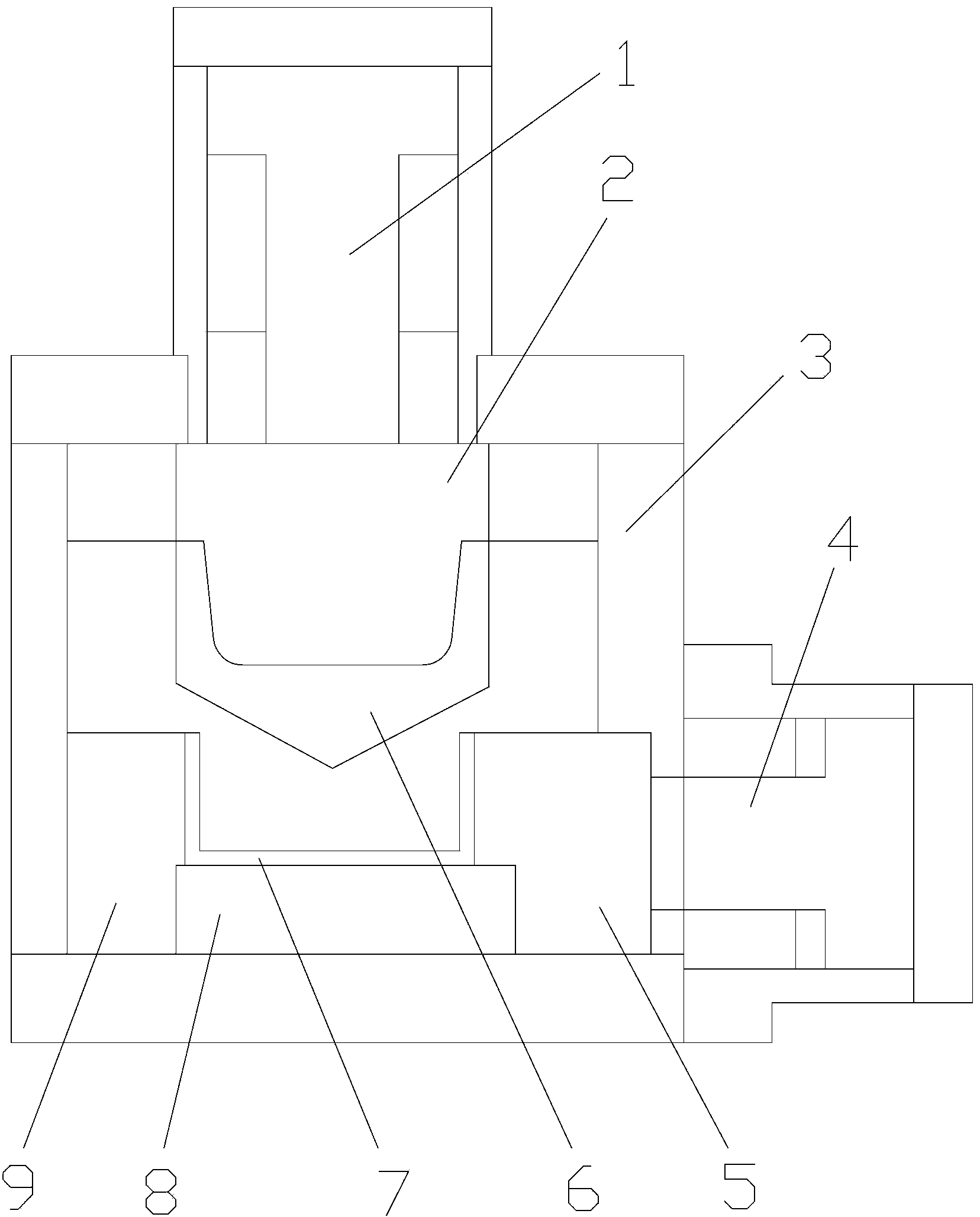
[0016] Such as figure 1 As shown, a hydraulic channel steel cutting machine includes a frame 3, the upper end of the frame 3 is provided with an upper hydraulic press 1, the lower end of the upper hydraulic press 1 is fixedly connected to the upper knife rest 2, the upper knife 6 is installed at the lower end of the upper knife rest 2, and the frame 3 A side hydraulic press 4 is arranged laterally on the side, and two movable knives 5 are installed on the front end of the side hydraulic press 4, and also includes a bottom knife 8 set opposite to the upper knife 6, a lower knife 9 set opposite to the movable knife 5, a bottom knife 8 and a lower knife 9 Be fixed on the frame 3, the lower end of the upper knife 6 is shaped ...


PUM


Abstract

The invention relates to a hydraulic channel-steel cutting machine and belongs to the field of hydraulic cutting machines. The hydraulic channel-steel cutting machine comprises a rack and is characterized in that the upper end of the rack is provided with an upper hydraulic machine; the lower end of the upper hydraulic machine is fixedly connected with an upper knife rest; an upper knife is arranged at the lower end of the upper knife rest; a side hydraulic machine is horizontally arranged at the side surface of the rack; two movable knives are arranged at the front end of the side hydraulic machine. The hydraulic channel-steel cutting machine also comprises bottom knives opposite to the upper knife and lower knives opposite to the movable knives; the bottom knives and the lower knives are fixed on the rack; a knife point is arranged at the lower end of the upper knife. The hydraulic channel-steel cutting machine provided by the invention is applicable to cutting channel steel, is especially good in cutting effect of U-shaped channel steel, and has the advantages that the channel steel can be fixed by the movable knives and the lower knives, and the cutting is carried out from the inner part of the channel steel by the upper cutting knife, so that the cutting stability is good and no deformation of the channel is caused.

Description

Technical field: [0001] The invention relates to a hydraulic cutting machine, in particular to a hydraulic channel steel cutting machine. Background technique: [0002] In the prior art, a punch is used to cut steel, but there are too many types and specifications of the same channel steel, including national standard, non-standard, heavy, light, etc. Different channel steel needs to be replaced with different molds, which is very inconvenient to use and the cutting effect is not ideal , The punch press is bulky and heavy, and cannot be moved casually, which brings a lot of inconvenience to production and low work efficiency. Invention content: [0003] The technical problem to be solved by the present invention is to provide a hydraulic channel steel cutting machine to solve the problems of low working efficiency and inconvenient use of punch presses for cutting channel steel. [0004] The technical problem to be solved by the present invention adopts the following techn...

Claims


Application Information

Patent Timeline
IPC IPC(8): B23D15/14B23D15/00B23D33/02
Inventor 章兵
Owner 章兵
Why Eureka
Try Eureka