Completely-forming computerized flat knitter compound needle

A computerized flat knitting machine and fully formed technology, which is applied in knitting, textiles and papermaking, etc., can solve problems such as loop transfer and knitting instability, loop transfer and overall knitting work cannot be normal

Active Publication Date: 2013-12-18
SHAOXING DAWEI KNITTING MACHINERY
View PDF12 Cites 1 Cited by
  • Summary
  • Abstract
  • Description
  • Claims
  • Application Information

AI Technical Summary

Problems solved by technology

[0005] However, the loop transfer needle with the above structure mainly realizes loop transfer through the cooperation of the needle latch or the loop transfer spring with a similar function to the main loop transfer needle. There will be frequent high-speed relative motion between the needle body of the transfer needle and the transfer needle. During the impact process, the impact force will have a great impact on the normal knitting work, so that the transfer and the overall knitting work cannot be carried out normally and smoothly. In the patent CN1470697A, although the setting of the slit reduces the lateral offset of the needle body in the needle groove, which alleviates the degree of offset to a certain extent, but because the relative movement displacement between the needle body and the needle groove is relatively large, this This improvement did not fundamentally solve the problems of circle shifting and unstable compilation work

Method used


Image

  • Completely-forming computerized flat knitter compound needle
  • Completely-forming computerized flat knitter compound needle
  • Completely-forming computerized flat knitter compound needle

Examples


Embodiment Construction

[0118] The present invention is described in further detail below in conjunction with the accompanying drawings and specific embodiments:

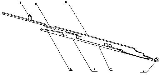
[0119] see figure 1 and attached Figure 4-6 , the present invention is applied to a compound needle of a fully-shaped computerized flat knitting machine, including a needle bar A and a needle core B, the needle bar A consists of a needle hook 1, a connecting part 2 and a needle tail 3 in turn, a needle hook 1, a connecting part 2 and a needle The tail 3 is made in one piece, the needle tail 3 is provided with a guide groove 4, and the needle bar A is connected to the bottom needle through the guide groove 4; A needle butt 9 is arranged at the tail of the needle butt 9, and a U-shaped groove 8 is arranged on the core body 7 between the needle butt 9 and the sliding part 6; The needle core B can slide in the connecting part 2 of the needle bar A through the sliding part 6, the needle hook 1 is located at one end of the loop transfer part...


PUM


Abstract

The invention relates to a high-performance computerized flat knitter compound needle, in particular to a completely-forming computerized flat knitter compound needle. The completely-forming computerized flat knitter compound needle comprises a needle rod and a needle core. The needle rod sequentially comprises a needle hook, a connecting part and a needle tail which are integrated. A guide groove is formed in the needle tail. The needle rod is connected with a bottom needle through the guide groove. The needle core sequentially comprises a stitch transfer part, a slide part and a core body. A needle butt is disposed at the tail of the core body. A U-shaped groove is formed in the core body between the needle butt and the slide part. The needle rod and the needle core are mounted in a compound manner. The slide part is nested into the connecting part. The needle core can slide in the connecting part of the needle rod through the slide part. The needle hook is located at one end of the stitch transfer part. The needle tail is located at the needle butt end. The compound needle meeting completely-forming knitting process requirements is simple in structural design, stable in operation, and the like.

Description

technical field [0001] The invention relates to a high-performance computerized flat knitting machine compound needle, in particular to a fully-shaped computerized flat knitting machine compound needle. Background technique [0002] In order to realize the diversified production requirements of high-end knitted sweater products, the flat needle, tuck or float knitted by ordinary computerized flat knitting machines alone cannot meet the knitting requirements of fully formed sweater products. Usually, the sweater pieces knitted by ordinary computerized flat knitting machines must be sewn on the sewing machine to form a complete sweater. In order to realize the one-time forming and knitting of the sweater fabric on the computerized flat knitting machine, it is necessary to configure a compound needle suitable for full-form knitting in the computerized flat knitting machine, so that it can carry out the sweater retracting and releasing needle under the combined action of the cam...

Claims


Application Information

Patent Timeline
Patent Type & Authority Applications(China)
IPC IPC(8): D04B35/06
Inventor 俞云泉俞峰方园张鑫君程志江赵树超
Owner SHAOXING DAWEI KNITTING MACHINERY
Why Eureka
Try Eureka