Vertical shaft TBM device

A shaft and cutter head technology, applied in mining equipment, earthwork drilling, tunnels, etc., can solve the problems of low construction efficiency of shafts, achieve reasonable force, improve efficiency, and prolong life

Active Publication Date: 2013-12-18
CHINA RAILWAY ENGINEERING EQUIPMENT GROUP CO LTD
View PDF4 Cites 11 Cited by
  • Summary
  • Abstract
  • Description
  • Claims
  • Application Information

AI Technical Summary

Problems solved by technology

[0003] The purpose of the present invention is to provide a shaft TBM device to solve the problem of low shaft construction efficiency in the prior art

Method used


Image

  • Vertical shaft TBM device
  • Vertical shaft TBM device
  • Vertical shaft TBM device

Examples


Embodiment Construction

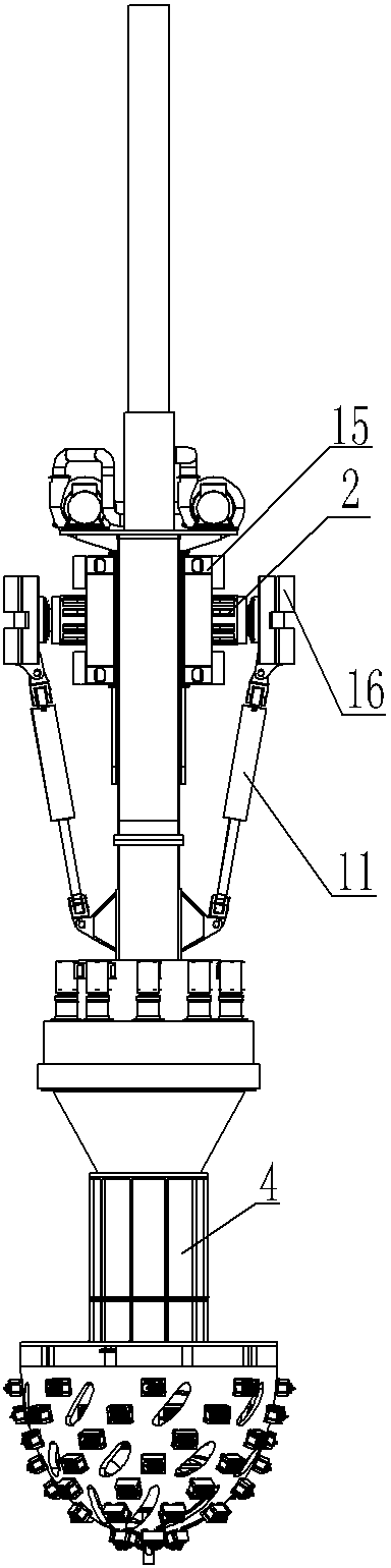
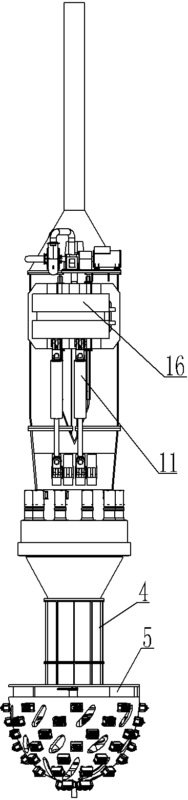
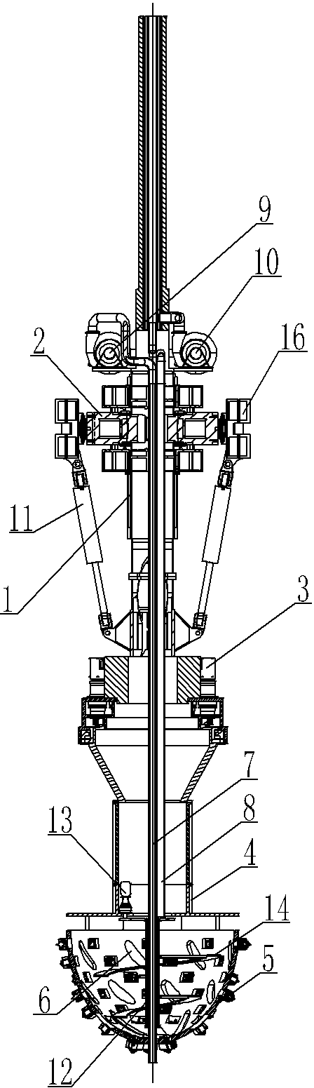
[0018] A kind of embodiment of shaft TBM device, in figure 1 , figure 2 as well as image 3 Among them, a cutter head drive system 3 is provided at the front of the main beam 1, where the cutter head drive system 3 is a gear drive system, which has a drive gear driven by a drive motor, and the drive motor is fixed on the main beam 1. The main bearing is fixed together with the rear portion of the connecting cylinder 4. In this way, the drive motor can drive the connecting cylinder 4 to rotate through the main bearing. A cutter head 5 is arranged at the front end of the connecting cylinder 4, where the cutter head 5 is half an ellipsoid, and the front end of the cutter head 5 is a sharper end of the ellipsoid. The inside of the cutter head 5 has a closed cavity, and a sealing plate is arranged at the rear end of the cutter head cavity, so that the cutter head 5 has a closed cavity. Cutters are arranged on the outer surface of the cutter head 5, and each cutter is arranged ...


PUM


Abstract

The invention discloses a vertical shaft TBM (Tunnel Boring Machine) device. The front part of a girder of the vertical shaft TBM device is provided with a cutter head driving system; rotation of the cutter head driving system drives a cutter head to rotate; the cutter head adopts a cavity-type hemi-ellipsoidal structure; a stirring device is arranged in a cavity of the cutter head; a cutter is arranged on the outer surface of the cutter head; a feed inlet is reserved on the cutter head; a slurry input pipeline and a slagging pipeline are arranged in the girder; the front end of the slurry input pipeline extends to the front end face of the cutter head; the rear end part of the cutter head is provided with the slagging pipeline communicated with the cavity of the cutter head; the rear end of the slagging pipeline extends out of the girder; both sides of the girder are provided with propelling systems; each propelling system comprises a thrust oil cylinder; one end of each thrust oil cylinder is hinged to the girder and the other end of the thrust oil cylinder extends backwards and is hinged with a supporting shoe; a telescopic oil cylinder for pressing two supporting shoes on the wall of a vertical shaft is arranged between the two supporting shoes. According to the invention, full-face integral forming of the vertical shaft can be implemented and the tunneling speed of the vertical shaft is greatly improved.

Description

technical field [0001] The invention relates to a mechanical device for shaft operation, in particular to a shaft TBM device. Background technique [0002] When excavating underground mineral deposits, it is necessary to excavate the ground to form shafts now. With the development of the national economy, there is an increasing demand for underground mineral deposits. The mining of underground mineral deposits has also changed from open-pit mining to underground mining, and the construction of shafts is also rapidly increase. But the shaft digging device does not improve along with the growth of the shaft construction project, and the shaft digging device in the prior art is still relatively backward. The current shafts are generally excavated manually from top to bottom. When a certain depth is reached, the walls are built from the bottom up. The excavation and wall building are carried out alternately. Sometimes it is necessary to spray grout on the well wall before t...

Claims


Application Information

Patent Timeline
Patent Type & Authority Applications(China)
IPC IPC(8): E21D9/08E21D9/00
Inventor 李建斌王锴贺飞
Owner CHINA RAILWAY ENGINEERING EQUIPMENT GROUP CO LTD
Why Eureka
Try Eureka