
Offshore hydroelectric generation platform

An offshore, platform technology, applied in ocean energy power generation, engine components, machines/engines, etc., can solve the problem of wave power generation that cannot be maneuvered in water, poor power generation effect, wave power generation device that cannot generate power, and single function, etc. problem, to achieve the effect of flexibility, improve power generation efficiency, and increase flow rate

Active Publication Date: 2013-12-18
ZHEJIANG OCEAN UNIV
View PDF2 Cites 4 Cited by
  • Summary
  • Abstract
  • Description
  • Claims
  • Application Information

AI Technical Summary

Problems solved by technology

[0003] The first object of the present invention is to provide an offshore hydropower platform that can float anywhere in the water area to generate electricity using waves, which solves the problem that the existing wave power generation device cannot be maneuverably installed in the water area The problem with generating wave power
[0004] The second purpose of the present invention is to further improve an offshore power generation platform with a wave inlet that can automatically face the waves on the basis of the first purpose, so as to solve the problem when the wave power generation device has an included angle with the direction of wave travel, especially The problem of poor power generation effect in back waves
[0005] The third object of the present invention is to further provide an offshore power generation platform capable of generating electricity by using the undercurrent in the water area on the basis of the first object and / or the second object, so as to solve the problem that the wave power generation device cannot use the The problem of power generation and single function of the water flow

Method used


Image

  • Offshore hydroelectric generation platform
  • Offshore hydroelectric generation platform
  • Offshore hydroelectric generation platform

Examples


Embodiment 1

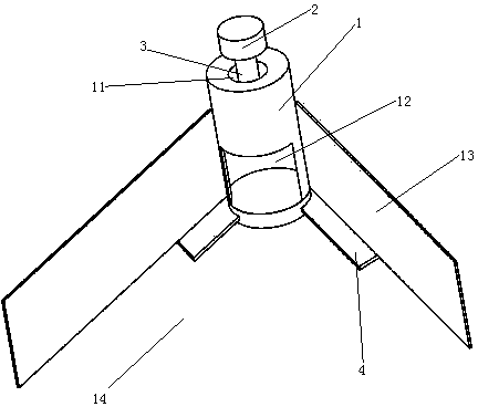
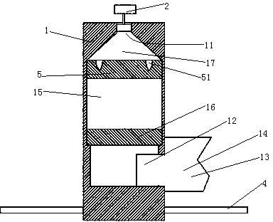
[0030] Embodiment one, see figure 1 , an offshore hydroelectric power generation platform, including a buoy 1 and a generator 2. The upper end of the buoy 1 is provided with an air inlet and outlet 11 . An air impeller 3 is installed in the air inlet and outlet 11 . The air impeller 3 is a two-way air impeller. Air turbine 3 and generator 2 are connected together.

[0031] The side lower end of the buoy 1 is provided with a wave inlet 12 and a balance wing 4 . Wave collecting plates 13 are arranged on both sides of the wave inlet 12 in the horizontal direction. A "V" shaped wave gathering groove 14 aligned with the wave inlet 12 is formed between the wave collecting plates 13 . Stabilizer 4 has 4 pieces. The balance wings 4 are distributed along the circumferential direction of the buoy 1 .

[0032] see figure 2 , The interior of the buoy 1 constitutes the air chamber 15 . The air inlet and outlet 11 are located at the top of the air chamber 15 . The wave inlet 12 i...

Embodiment 2

[0037] Embodiment two, see Figure 6 , also includes a wave inlet transposition motor 7, a wave inlet transposition motor control unit 71, a wave flow direction sensor 72, a water current generating mechanism 8 and a power coupling mechanism 9. Both the wave flow direction sensor 72 and the water current generating mechanism 8 are electrically connected with the wave inlet transposition motor control unit 71 .

[0038] The buoy 1 is sequentially provided with a base 18 , a rotating section 19 and a fixed section 10 from bottom to top. The fixed section 10 and the base 18 are fixed together, and the rotating section 19 can rotate relative to the base 18 .

[0039] Balance wing 4 is fixed on the base 18. A positioning pendant 41 is suspended on the balance wing 4 . Wave inlet transposition motor 7 is installed on the base 18.

[0040] The wave inlet 12 and the wave collecting plate 13 are arranged on the rotating section 19 . The air chamber 15 is provided with an arc-shape...


PUM


Abstract

The invention relates to hydroelectric equipment, in particular to an offshore hydroelectric generation platform comprising a buoy and a generator. The buoy is provided with a gas chamber inside and a piston inside the gas chamber. The lower end of the gas chamber is provided with a wave inlet. The upper end of the gas chamber is provided with a gas access hole. The piston locates between the gas access hole and the wave inlet. The gas access hole is provided with an air turbine driving the generator. Wave collection plates are arranged on two sides of the wave inlet in the horizontal direction. A 'V'-shaped wave collection channel forms between the wave collection plates. The offshore hydroelectric generation platform can float at any position in a water area to generate power by waves; the problem that the existing wave power generation device cannot be flexibly disposed in the water area to generate power by waves is solved.

Description

technical field [0001] The invention relates to hydropower equipment, in particular to an offshore hydroelectric power generation platform. Background technique [0002] There are many hydroelectric devices that harness the power of water to generate electricity. According to the power, it can be divided into two categories: one is hydroelectric equipment that uses wave energy to generate electricity (hereinafter referred to as wave power generation device), such as the Chinese patent number 201220645685, and the date of authorization announcement is May 29, 2013 The Japanese patent document titled "shore-based wave power generation device" discloses a device installed on the shore using waves to generate power; another type is hydropower equipment that uses the kinetic energy of water flow to generate power (hereinafter referred to as water power generating device), such as a power station. The existing wave power generation device has the following disadvantages: it ...

Claims


Application Information

Patent Timeline
Patent Type & Authority Applications(China)
IPC IPC(8): F03B13/14
CPCY02E10/30
Inventor 陈正寿刘羽赵陈孙孟
Owner ZHEJIANG OCEAN UNIV
Learn More