Non-contact mechanical seal ring with dual-rotating-direction hydrodynamic grooves

A fluid dynamic pressure and mechanical sealing technology, which is applied in the direction of engine sealing, mechanical equipment, engine components, etc., can solve the problem of low leakage

Active Publication Date: 2013-12-18
SICHUAN SUNNY SEAL
View PDF7 Cites 11 Cited by
  • Summary
  • Abstract
  • Description
  • Claims
  • Application Information

AI Technical Summary

Problems solved by technology

The hydrodynamic pressure groove on the sealing end surface of the single-rotation sealing ring is typically characterized by a logarithmic helix or Archimedes line, and has the advantages of significant hydrodynamic pressure effect, low leakage, and good fluid film stiffness. , but limited by the geometrical characteristics of the groove, this type of groove can only be used in the case of unidirectional rotation

Method used


Image

  • Non-contact mechanical seal ring with dual-rotating-direction hydrodynamic grooves
  • Non-contact mechanical seal ring with dual-rotating-direction hydrodynamic grooves

Examples


Embodiment 1

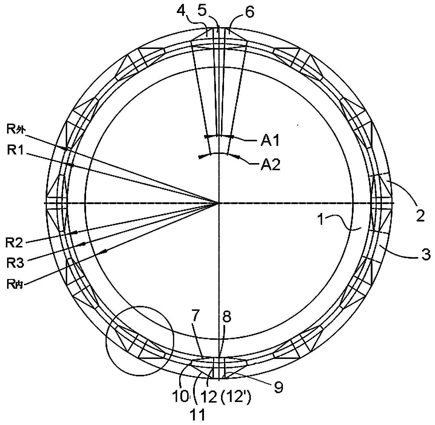
[0030] As shown in the figure, the non-contact mechanical seal ring of the present invention with double-rotation fluid dynamic pressure grooves has an inner diameter R inner = 401.62mm and an outer diameter R outer = 517.68mm on the sealing end face, and its R3 = 455.04mm The outer part is the sealing groove area 2, in which there are several ( figure 1 Shown in is 12) the same form of fluid dynamic pressure groove structure unit, the interval between each fluid dynamic pressure groove structure unit is the sealing platform area 3, the inner circumference of the sealing groove area 2 is a structure without dynamic pressure groove Unit sealing dam area 1. among them:

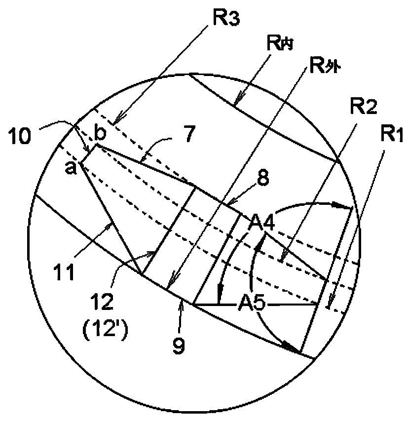
[0031] ——Each fluid dynamic pressure groove structural unit is a "wing-shaped" structure composed of a central groove 5 and wing grooves 4 and 6 of the same structure that are joined to it on both sides of its circumference and extend symmetrically and convergently to both sides. The dynamic pressure groove group....

Embodiment 2

[0038] The non-contact mechanical seal ring of the double-rotation fluid dynamic pressure groove of this example is based on the structure of embodiment 1. The depth of the central groove 5 is changed from equal depth to arc-shaped inner wall edge 8 to increase linearly from the peripheral wall opening 9 The groove depth of the peripheral wall opening 9 at the outer diameter is 24 microns, and the groove depth at the 8 end of the arc-shaped inner wall is 5 microns equal to the depth of the wing groove. The dynamic pressure effect of the non-equal depth wedge-shaped central groove is similar to that of Example 1, but the static pressure opening effect is better, but the static pressure leakage is also increased accordingly.


PUM


Abstract

The invention provides a non-contact mechanical seal ring with dual-rotating-direction hydrodynamic grooves. Hydrodynamic groove structure units in same forms are arranged on the outer side of a seal end face circumferentially at equal intervals; the hydrodynamic groove structure unit is in a wing-shaped structure formed by a central groove and same wing grooves which are connected to two sides of the central groove respectively and which extend symmetrically in a converged manner; the central groove and two wall edges thereof are two radial extending segments of the seal end face respectively, the wall edge on the inner side is an arc concentric with the seal end face, and the central groove is formed in the circumferential wall of a seal ring body, long side edges of two sides of the wing grooves and short grooves at the converged-extending ends are two radial extending segments of the seal end face; the long side edges of two sides of the wing grooves fit and are connected with the side wall of the central groove where the same located. By the aid of the hydrodynamic groove structure, seal hydrodynamic effect can be improved, seal end face opening force is increased, thickness and strength of the fluid film between the seal end faces are increased, seal leakage is reduced, groove processing difficulty is reduced, and process requirements on seal parts processing and assembling are lowered.

Description

technical field [0001] The invention relates to a seal ring which can be used for the shaft end seal of various forms of compressors, expanders, pumps, reactors and other rotary machines. Background technique [0002] The non-contact mechanical seal on the fluid end face uses two relatively rotating seal rings to shear the fluid between the two rings during rotation to form a hydrodynamic pressure effect, thereby increasing the bearing capacity and rigidity of the fluid film on the end face. Finally, the sealing end face is in a stable non-contact state for a long time. Changing the groove shape of the hydrodynamic pressure groove provided on the sealing end surface is an effective and common means to enhance the hydrodynamic pressure effect of the end surface, reduce the leakage of the seal and prolong the service life of the seal. [0003] Fluid end face non-contact mechanical seals are usually divided into two categories: single rotation and double rotation. The hydrod...

Claims


Application Information

Patent Timeline
Patent Type & Authority Applications(China)
IPC IPC(8): F16J15/40
Inventor 陈侃黄泽沛张车宁王泽平刘小明张智
Owner SICHUAN SUNNY SEAL
Why Eureka
Try Eureka