Method and system for three-dimensional measurement of complex curved surface parts with multi-optical sensors

An optical sensor and complex surface technology, applied in the field of precision measurement, can solve the problems of difficult normal measurement, low measurement accuracy of special measuring tools, and inability to meet full inspection and full inspection.

Inactive Publication Date: 2016-01-20
HEILONGJIANG UNIVERSITY OF SCIENCE AND TECHNOLOGY
View PDF8 Cites 0 Cited by
  • Summary
  • Abstract
  • Description
  • Claims
  • Application Information

AI Technical Summary

Problems solved by technology

None of them can fully meet the accurate measurement of parameters such as blade section line, twist angle, bend angle and chord length, especially the radius of the leading and trailing edges.
Moreover, these two methods also have the following problems. The measurement accuracy of the special measuring tool is low and the labor intensity is high; each type of blade needs to manufacture multiple sets of measuring tools, which is high in cost, long in cycle, and difficult to manufacture.
The three-coordinate measurement can only measure a limited number of profiled lines of the blade section, and the obtained information is limited (the two profiles may be out of tolerance); when measuring the blade, due to the three-axis linkage, it is difficult to fully realize the normal measurement, and the method The direction error compensation algorithm is complex and the accuracy is poor; it is difficult to achieve accurate measurement at places with severe curvature changes (such as the front and rear edges of the blade); the cost is high and the cycle is long (especially for large-size blades), and it takes about 30-40 minutes to obtain basic data It takes several hours or even longer to obtain all the data, and the current method cannot meet the needs of full testing and full testing

Method used


Image

  • Method and system for three-dimensional measurement of complex curved surface parts with multi-optical sensors
  • Method and system for three-dimensional measurement of complex curved surface parts with multi-optical sensors
  • Method and system for three-dimensional measurement of complex curved surface parts with multi-optical sensors

Examples


Embodiment Construction

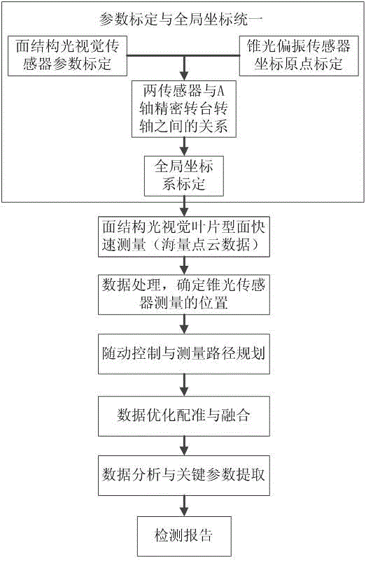
[0028] The working principle of the measurement method of the present invention is as follows: first, the global coordinate system calibration is carried out on the combined measuring head, so that the surface structured light visual sensor and the cone light polarization holographic sensor work in the same coordinate system; then the surface structured light in the combined optical measuring head is used to The visual sensor quickly measures the complex surface parts, obtains massive 3D point cloud data of the parts, processes the point cloud data, and determines the holes and discontinuous areas of the measurement data. The 4-axis control system drives the conoscopic polarization holographic sensor to move to the corresponding The position is precisely measured, and the complete point cloud data of the part is finally obtained. workflow such as figure 1 .

[0029] Measurement method provided by the invention comprises the steps:

[0030] Step 1, calibrate the parameters of...


PUM


Abstract

The invention provides a method and device for three-dimensionally measuring complex curved surface parts through multi-optical-sensor cooperation. The problems of accuracy, efficiency and data integrity when optical measurement is conducted on the complex curved surface parts are solved. According to the method, surface structured light is utilized to conduct quick measurement on reflective complex curved surfaces, measured data measured and acquired by surface structured light are divided, measured data holes and discontinuous zones are determined, secondary measurement is conducted on the data holes and the discontinuous zones by a conoscopic holographic measuring head, point cloud data measured by a surface structured light visual sensor and a conoscopic holographic sensor are integrated in a same coordinate system through a global calibration and optimization registration method of the multiple sensors, and eventually integral three-dimensional point cloud data of the parts are acquired. The measuring system comprises a precise four-axis motion control system and a combination optical measuring head. High-efficiency and high-accuracy measurement for the reflective complex curved surface parts is achieved.

Description

technical field [0001] The invention belongs to the field of precision measurement, and in particular relates to a multi-optical sensor collaborative fast and precise three-dimensional measurement system and method. It is especially suitable for non-contact rapid and precise measurement of complex curved surface parts such as aero-engines and gas turbine blades. technical background [0002] Due to the high-performance surface and complex shape of parts with complex curved surfaces, the measurement is difficult. The existing technology cannot simultaneously achieve the purpose of high-precision, high-efficiency and non-coating measurement. For example, the blade is an extremely critical part of an aero engine and a gas turbine. Its working environment is very harsh, and it bears multiple loads such as aerodynamic force and centrifugal force at the same time. Any manufacturing defect will affect the final working efficiency and service life of the engine. Therefore, more and...

Claims


Application Information

Patent Timeline
Patent Type & Authority Patents(China)
IPC IPC(8): G01B11/24
Inventor 赵灿何万涛车向前孟祥林张海录梁永波程俊廷李景贺
Owner HEILONGJIANG UNIVERSITY OF SCIENCE AND TECHNOLOGY
Why Eureka
Try Eureka