Three-dimensional imaging method using multi-pulse order emitting

A three-dimensional imaging and multi-pulse technology, applied in the field of array imaging, can solve the problems of complex coding signal waveform, low robustness, and unfavorable use of MIMO array three-dimensional imaging system, and achieve the effect of saving array elements

Inactive Publication Date: 2015-07-08
NORTHWESTERN POLYTECHNICAL UNIV
View PDF3 Cites 0 Cited by
  • Summary
  • Abstract
  • Description
  • Claims
  • Application Information

AI Technical Summary

Problems solved by technology

The waveforms of these encoded signals are relatively complex, and their robustness is lower than that of conventional continuous wave (CW, Continuous Wave) pulses and linear frequency modulation (LFM, Linear Frequency Modulation) pulses
This is not conducive to the use of MIMO array 3D imaging systems in complex environments

Method used


Image

  • Three-dimensional imaging method using multi-pulse order emitting
  • Three-dimensional imaging method using multi-pulse order emitting
  • Three-dimensional imaging method using multi-pulse order emitting

Examples


Embodiment Construction

[0021] The present invention will be further described below in conjunction with the accompanying drawings and embodiments, and the present invention includes but not limited to the following embodiments.

[0022] Main content of the present invention has:

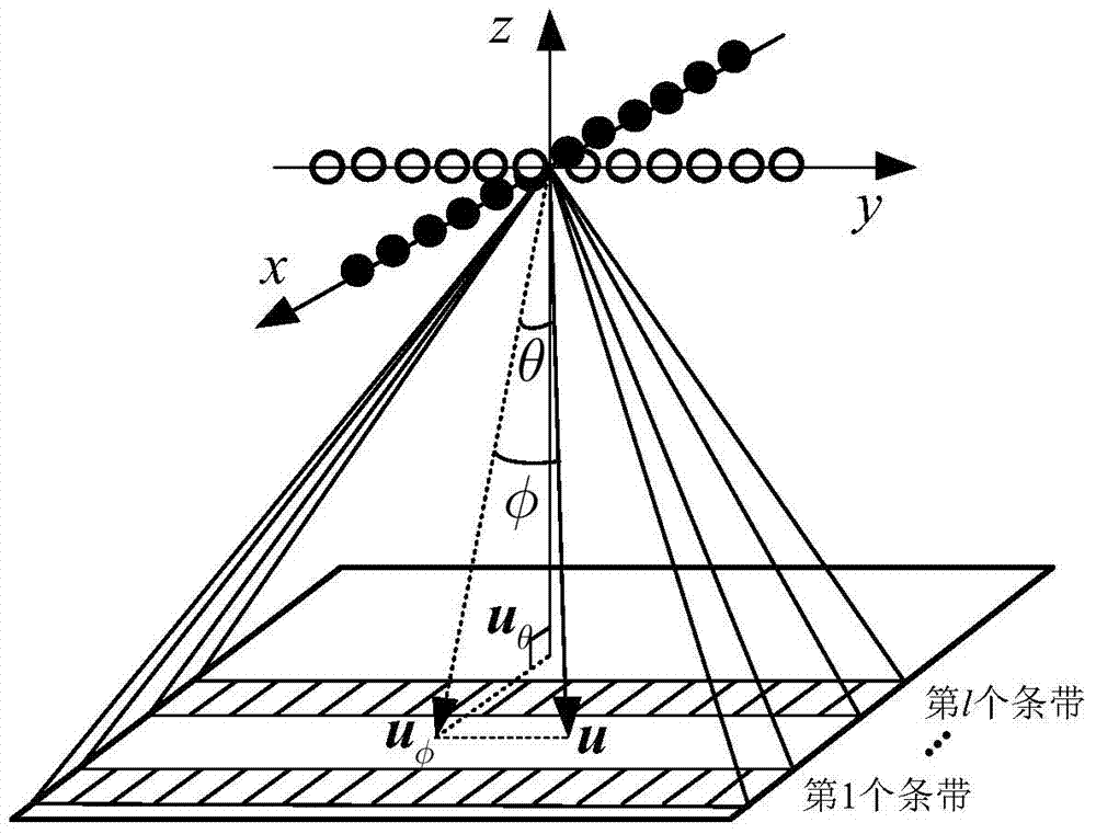
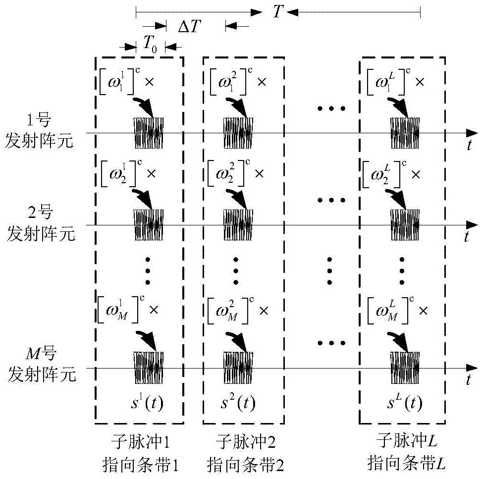
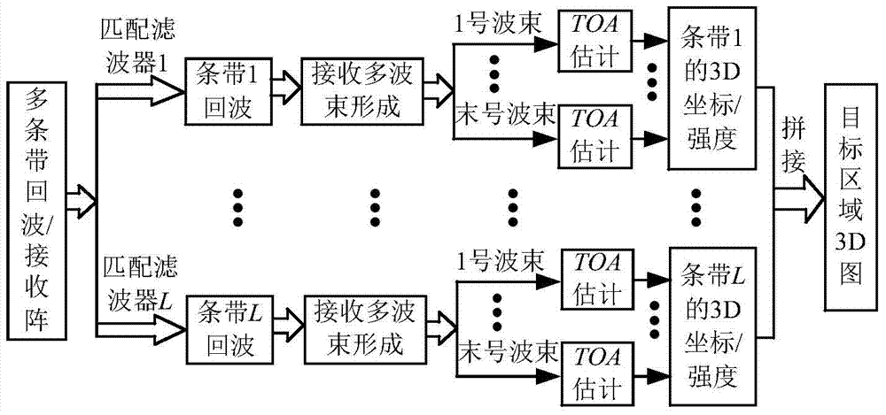
[0023] 1. Both the transmitting array and the receiving array are linear arrays, and the two are perpendicular to each other. The transmitting linear array transmits multiple independent pulses sequentially according to the working mode of the active phased array. These pulses are weighted before firing to illuminate different strips. At the receiving end, the echoes are matched filtered using a copy of the transmitted pulse to separate out all the banded echoes. Finally, processing such as beamforming is performed on the echoes of each strip to obtain a three-dimensional image of the target area.

[0024] 2. Through computer numerical simulation, the three-dimensional imaging method proposed in the present invention is...


PUM


Abstract

The invention provides a three-dimensional imaging method using multi-pulse order emitting. An emitting array and a receiving array are both linear arrays and are vertical to each other. The linear emitting array emits a plurality of independent pulses in order according to a work method of an active phase control array. Weighting is carried out on the pulses before emitting, so that different stripes are illuminated. At the receiving end, matched filtering processing is carried out on echoes by means of copying of emitted pulses so as to separate echoes of all the stripes. Finally, the echoes of the stripes undergo beam forming processing to obtain a three-dimensional image of a target area. A large quantity of array elements are saved, gain of the emitting array is obtained, and CM pulses or LFM pulses with simpler waveforms can be used.

Description

technical field [0001] The invention relates to an array imaging method. Background technique [0002] In the field of three-dimensional array imaging, in order to obtain a three-dimensional map of the imaging area, a rectangular planar array with spatial three-dimensional resolution can be used (Murino V and Trucco A, Three-dimensional image generation and processing in underwater acoustic vision, in Proc.IEEE, 2000; 88(12):103-1948.). However, the use of a planar array will bring the disadvantage of a large number of array elements, resulting in a high cost of the 3D imaging system. In order to save the number of array elements of the 3D imaging system and reduce the system cost, Wang Huaijun (Wang H J. Narrowband MIMO radar imaging with two orthogonal linear T / R arrays. In Proceeding of ICSP2008, Beijing, China, 2008: 2513-2516.) 、Wang D W, Ma X Y, Chen A L, and Su Y, High-resolution imaging using a wideband MIMO radar system with two distributed arrays, IEEE Trans. Ima...

Claims


Application Information

Patent Timeline
Patent Type & Authority Patents(China)
IPC IPC(8): G01S13/89
Inventor 孙超刘雄厚
Owner NORTHWESTERN POLYTECHNICAL UNIV
Why Eureka
Try Eureka