


Quick Research
Generate reliable direction feasibility study reports for your R&D in just a few steps.

Technical Q&A
Discover and master advanced knowledge NOW. Basics, ideas, possibilities, all at once.

Find Solutions
As an expert in R&D theories, this can generate solutions to your technical problems instantly.

Evaluate Feasibility
Analyze your overall solution with one click, know your potential R&D risks in advance.

Monitor Landscape
Get weekly tech updates, stay abreast of the latest tech innovations and key insights.
Mechanical dithering laser gyroscope light-combined adjusting system
A technology of laser gyro and adjustment system, applied in control/adjustment system, general control system, computer control and other directions, can solve the problems of rough, unstable manual operation, inaccurate judgment and calculation of signal waveform threshold parameters, etc., to improve efficiency and accuracy, accurate positioning, and improve the effect of intuitive judgment
- Summary
- Abstract
- Description
- Claims
- Application Information
AI Technical Summary
Problems solved by technology
Method used
Image

Examples
Embodiment 1
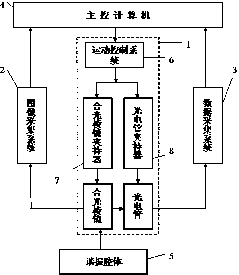
[0025] Example 1: see figure 1 To Figure 8, the mechanical dithering laser gyro light combining adjustment system is used to adjust the position of the light combining prism on the plane mirror of the resonant cavity and adjust the position of the photoelectric tube on the inclined surface of the light combining prism;
[0026] The mechanical dithering laser gyro light combining adjustment system is used to adjust the position of the light combining prism on the plane mirror of the resonant cavity and the position of the photoelectric tube on the inclined surface of the light combining prism. It is controlled by the light combining prism and the photoelectric tube assembly mechanism. The system (1), the image acquisition system (2), the data acquisition system (3) are composed of a main control computer (4) and a resonant cavity (5), and is characterized in that: the main control computer (4) is connected to Heguang Prism and photocell assembly mechanism and its control system (1)...
Embodiment 2
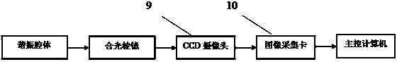
[0033] Example 2: see figure 2 This embodiment is basically the same as the first embodiment. The difference is that: the image acquisition system 2 is composed of a light combining prism, a CCD camera (9) and an image acquisition card (10). The CCD camera (9) is placed in the light combining prism. Above the inclined surface of the prism, the CCD camera (9) is connected with the image capture card (10), the model of the image capture card (10) is Daheng MER-500-7UM / UC-L, and the lens of the CCD camera (9) faces the combined light The output light of the prism, the image output end of the CCD camera (9) is connected to the image input end of the image capture card (10), and the image output end of the image capture card (10) is connected to the image input end of the main control computer (4). The other components and connection modes are the same as in the first embodiment.
Embodiment 3
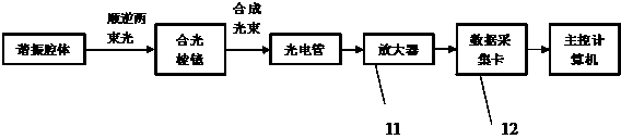
[0034] Example three: see image 3 This embodiment is basically the same as the first embodiment, but the difference is that the data acquisition system 3 includes a tuned light prism, a tuned phototube, a preamplifier (11), and a high-speed data acquisition card (7). The dimming tube is closely attached to the inclined surface of the light combining prism. The light window of the dimming tube collects the output light of the light combining prism. The phototube is connected to the preamplifier (11). The output end of the dimming tube is connected to the front The input end of the amplifier (11) and the output end of the preamplifier (11) are connected to the input end of the high-speed data acquisition card (7). The high-speed data acquisition card (7) is installed in the PCI slot of the main control computer (4), The model of the high-speed data acquisition card (7) is LDI320. Other components and connection modes are the same as the first embodiment. This real-time sampling...
PUM
 Abstract
Description
Claims
Application Information
 - R&D Engineer
- R&D Manager
- IP Professional
- Industry Leading Data Capabilities
- Powerful AI technology
- Patent DNA Extraction
Browse by: Latest US Patents, China's latest patents, Technical Efficacy Thesaurus, Application Domain, Technology Topic, Popular Technical Reports.
© 2024 PatSnap. All rights reserved.Legal|Privacy policy|Modern Slavery Act Transparency Statement|Sitemap|About US| Contact US: help@patsnap.com