Eureka AIR delivers breakthrough ideas for toughest innovation challenges, trusted by R&D personnel around the world.

Combination structure of electronic product shell and plastic part

A technology for electronic products and plastic parts, which is applied in the direction of electrical equipment casings/cabinets/drawers, electrical components, etc., which can solve problems such as complex processing, lower casing strength, and unevenness, and achieve good radiation protection effects, stable bonding, and light weight Effect

Inactive Publication Date: 2013-12-18
KUSN TONG YIN INDAL ELECTRONICS MAKING
View PDF3 Cites 3 Cited by
  • Summary
  • Abstract
  • Description
  • Claims
  • Application Information

AI Technical Summary

Problems solved by technology

[0002] The shell of traditional electronic products is made of plastic material, and the surface of the product will be uneven. Therefore, it is necessary to perform multiple grinding procedures before painting to meet the requirements of the shell panel. The processing is more complicated, and the radiation protection performance is not good.
There are still some shells made of metal materials on the market. This kind of metal shell is not easy to break, but the metal shell needs to be fixed on the metal, which reduces the strength of the shell and increases the thickness and weight of the shell.
There are also some shells made of composite materials such as carbon fiber or glass fiber on the market. The shells made of such composite materials have the advantages of high strength, thin thickness, light weight, corrosion resistance, etc., and have good radiation resistance. However, it cannot form complex structural parts, especially when combined with plastic parts with complex structures, it is necessary to increase the dielectric layer to realize the combination of electronic product shells and plastic parts, but this combination has defects such as instability and infirmity.

Method used


Image

  • Combination structure of electronic product shell and plastic part
  • Combination structure of electronic product shell and plastic part
  • Combination structure of electronic product shell and plastic part

Examples


Embodiment Construction

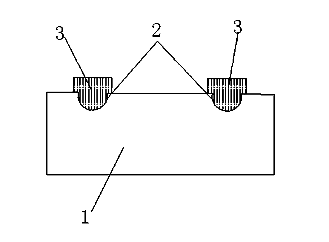
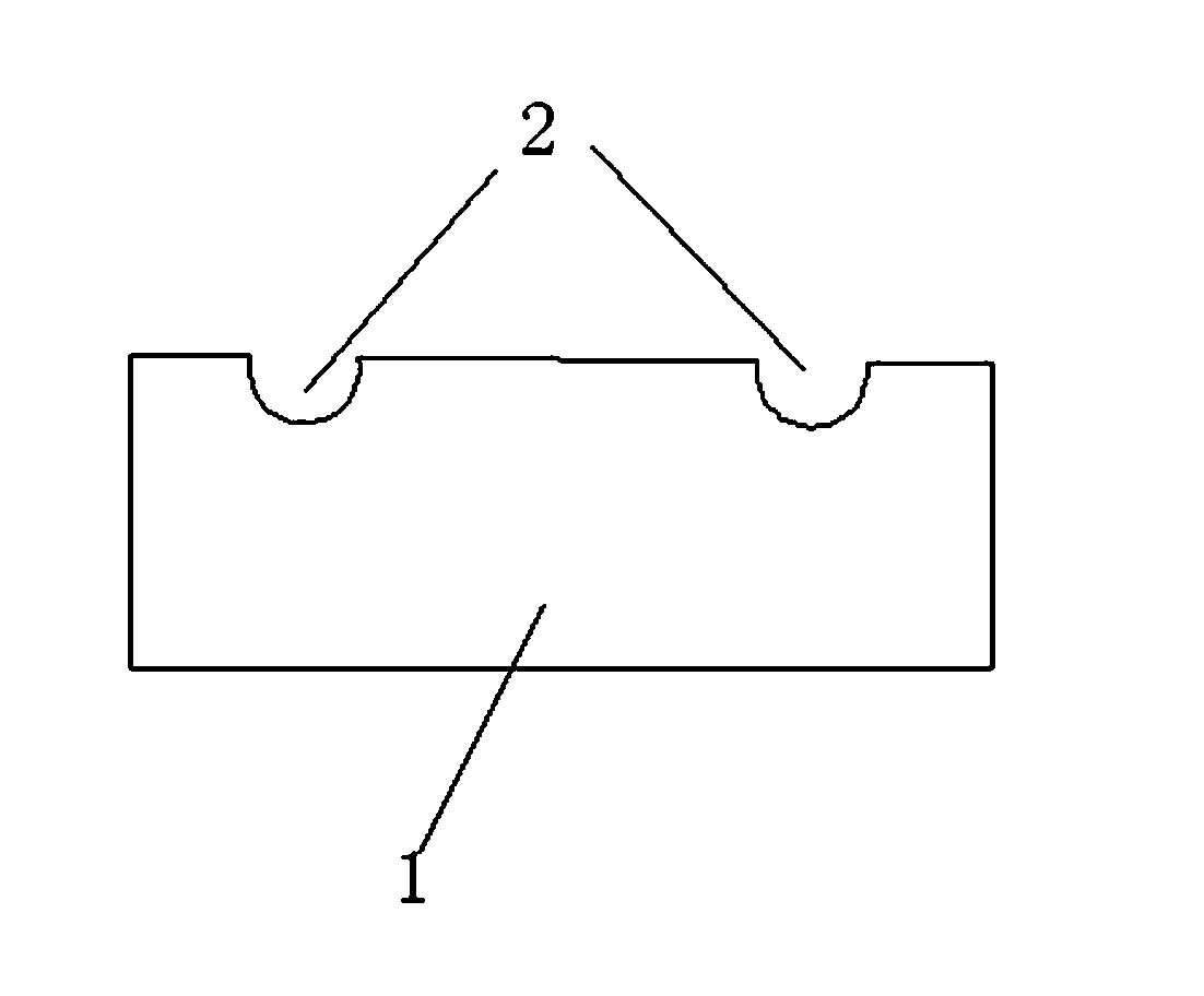
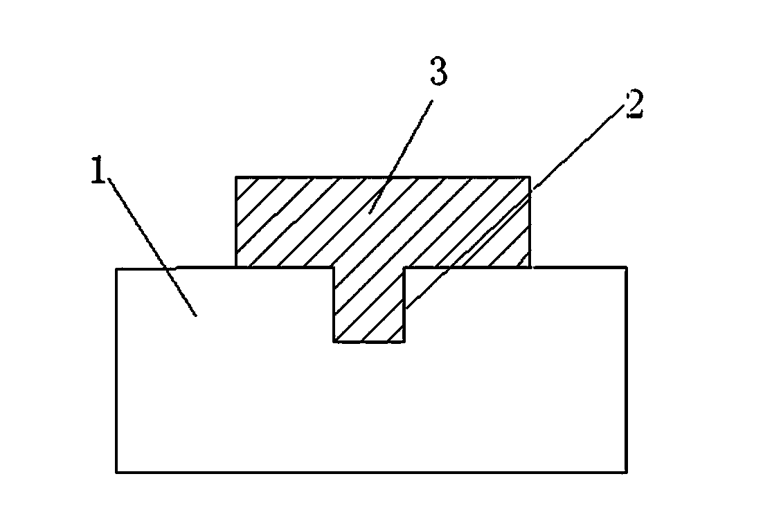
[0020] Such as figure 1 , figure 2 , image 3 , Figure 4 with Figure 5 As shown, a combination structure of an electronic product housing and a plastic part includes a housing base material 1 on which a groove 2 is provided, and a plastic part 3 is injection-molded in the groove 2. The piece 3 can cover the groove 2.

[0021] Preferably, the shell substrate 1 is one of metal, metal composite material and non-metal composite material.

[0022] Preferably, the non-metal composite material is one of carbon fiber composite material, glass fiber composite material and aramid composite material.

[0023] Preferably, the groove 2 is one of a round hole shape, a square hole shape and a zigzag shape, and a plastic with a complex structure can be formed by the hole-shaped groove or the zigzag groove and the insert injection molding process. After forming and combining, the plastic part and the electronic product housing are more stable. However, other shapes of groove structures and simil...


PUM


Abstract

The invention discloses a combination structure of an electronic product shell and a plastic part. The combination structure comprises a shell base material. A groove is formed in the shell base material, the plastic part is formed inside the groove in an injection molding mode, the plastic part can cover the groove, the shell base material is metal or a metal composite material or a non-metal composite material, and the groove is in the shape of a round hole or a square hole or a saw tooth. By means of the combination structure, combination of the electronic product shell and the plastic part can be well realized, and particularly the combination of a shell made of the composite materials such as carbon fibers or glass fibers and a complex structural part is better realized, so that the advantages, of being good in radiation-resistant effect, high in strength, small in thickness, low in weight, corrosion resistant, high temperature resistant and attractive, of the composite materials are reserved in the shell, the plastic part of a complex structure is formed by the hole-shaped groove or the saw-tooth-shaped groove through an insert injection molding technology, and after forming and combining, the combination of the plastic part and the electronic product shell is more stable.

Description

Technical field [0001] The invention relates to a shell structure of an electronic product, in particular to a combination structure of an electronic product shell and a plastic part. Background technique [0002] The shell of traditional electronic products is made of plastic materials, and the surface of the product is not smooth. Therefore, it needs to be polished several times before baking to meet the requirements of the shell panel. The processing is more complicated and the radiation protection performance is not good. There are also some shells made of metal materials on the market. These metal shells are not easy to break, but the metal shells need to be fixed in the metal, which reduces the strength of the shell and increases the thickness and weight of the shell. . There are also some shells made of composite materials such as carbon fiber or glass fiber on the market. The shells made of such composite materials have the advantages of high strength, thin thickness, li...

Claims


Application Information

Patent Timeline
Patent Type & Authority Applications(China)
IPC IPC(8): H05K5/00
Inventor 魏宏帆
Owner KUSN TONG YIN INDAL ELECTRONICS MAKING
Why Eureka
Eureka Blog
Learn More