Hard surface cleaner
A hard surface and cleaner technology, applied in the field of cleaners, can solve the problems of inconvenient cleaning, no liquid spray function, and inability to realize sewage recycling, etc., and achieve the effect of novel structure
- Summary
- Abstract
- Description
- Claims
- Application Information
AI Technical Summary
Problems solved by technology
Method used
Image

Examples
Embodiment 1
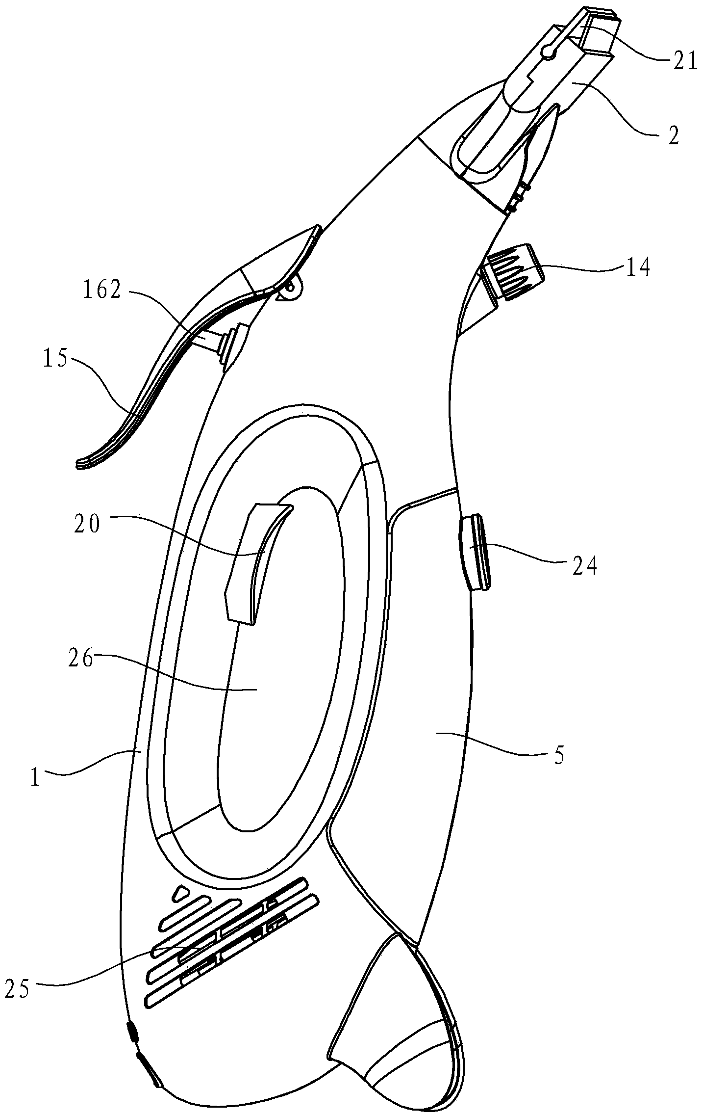
[0037] Embodiment one: if Figure 1 to Figure 9As shown, a suction nozzle 2 is installed on the top of the housing 1 of the hard surface cleaner in this embodiment, and the suction nozzle 2 includes two flexible scraping strips 22, and suction is formed between the tops of the flexible scraping strips 22. The suction port 21 of the mouth. The interior of the housing 1 is divided into a separation chamber 6 at the top and an accommodating chamber 7 at the bottom by a partition 28. The gas-liquid separation mechanism 3 is installed in the separation chamber 6 and is located below the outlet 23 of the suction nozzle 2. The suction The device 4 and the liquid storage container 5 are installed in the accommodation chamber 7 .
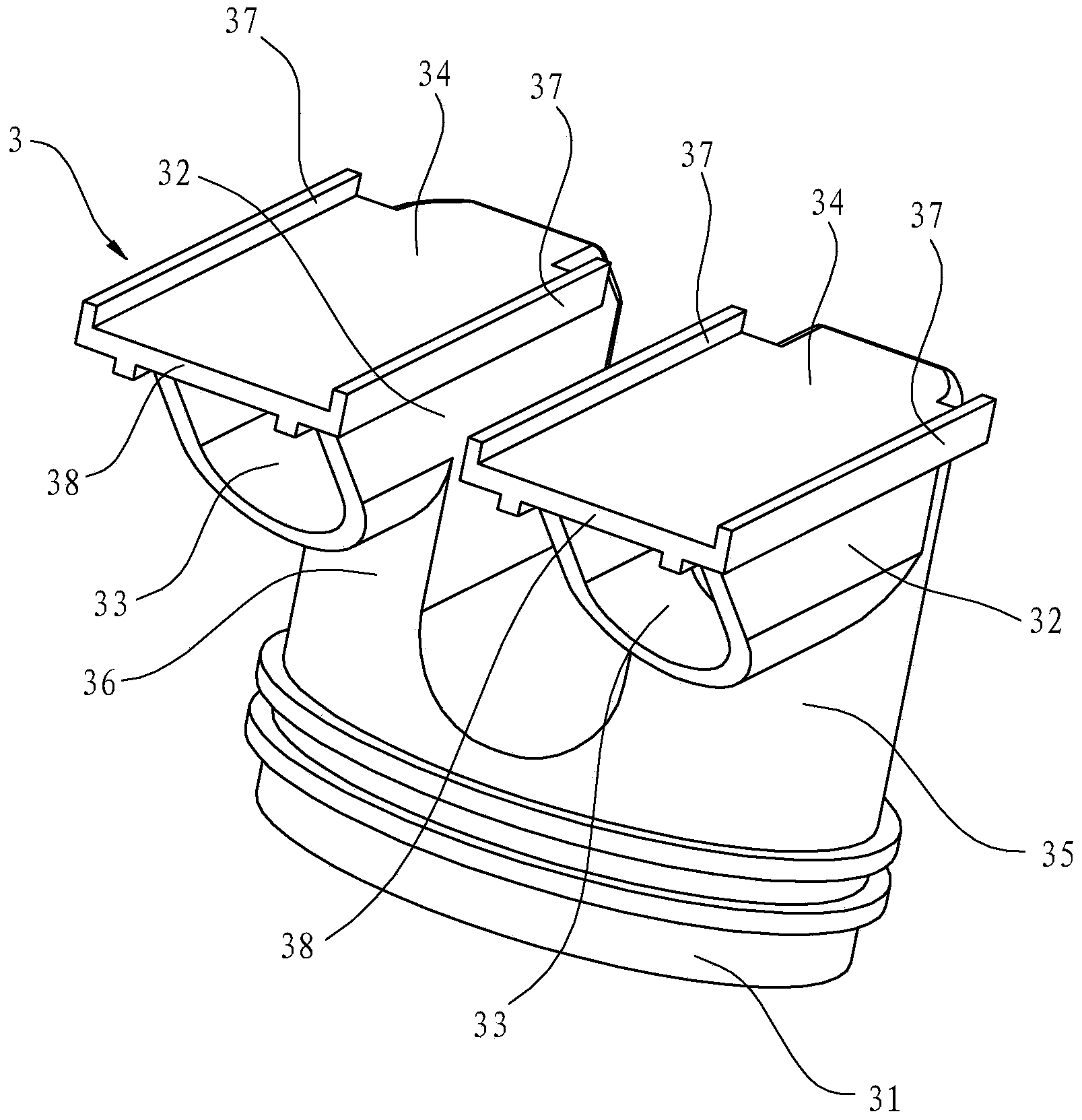
[0038] Such as figure 2 As shown, the gas-liquid separation mechanism 3 includes a longitudinal portion constituting an air outlet passage 31 and a transverse portion constituting an air inlet passage 32. The upper end of the air outlet passage 31 forms a...
Embodiment 2
[0044] Embodiment two: if Figure 10 As shown, the filter device of this embodiment includes a filter core 11 installed in the liquid inlet channel 91 of the flow guiding device 9, the filter core 11 adopts a filter strip made of filter material, and the filter material can be activated carbon, quartz sand or ceramics particles etc. When the cleaner is working, the gas-liquid mixture inhaled from the suction port 21 of the suction nozzle 2 is separated by the gas-liquid separation mechanism 3 in the separation chamber 6, and the separated water flows into the liquid inlet channel 91 and is filtered by the filter in the liquid inlet channel. The core 11 performs filtration and finally flows into the liquid storage container 5 . In addition, except that the filtering device of this embodiment is different from that of Embodiment 1, the rest of the structure of the cleaner is the same as that of Embodiment 1, and will not be described in detail here.
Embodiment 3
[0045] Embodiment three: as Figure 11 and Figure 12 As shown, the filter device of this embodiment includes a filter cartridge 12 installed inside the liquid storage container 5 , and a liquid-taking pipe (not shown in the figure) is provided between the outer wall of the filter cartridge 12 and the inner wall of the liquid storage container 5 . The filter cartridge 12 adopts pp filter cotton or non-woven filter cotton as the filter material, the upper port of the filter cartridge 12 is installed on the top of the liquid storage container 5 inner wall, and the lower port of the filter cartridge 12 is installed on the bottom of the liquid storage container 5 inner wall, A filter hole 121 is opened on the cylinder body of the filter cartridge 12, and the diameter of the filter hole 121 is also in micron order. When the cleaner is working, the gas-liquid mixture inhaled from the suction nozzle 2 is separated by the gas-liquid separation mechanism 3 in the separation chamber 6,...
PUM
 Abstract
Description
Claims
Application Information
 - R&D
- Intellectual Property
- Life Sciences
- Materials
- Tech Scout
- Unparalleled Data Quality
- Higher Quality Content
- 60% Fewer Hallucinations
Browse by: Latest US Patents, China's latest patents, Technical Efficacy Thesaurus, Application Domain, Technology Topic, Popular Technical Reports.
© 2025 PatSnap. All rights reserved.Legal|Privacy policy|Modern Slavery Act Transparency Statement|Sitemap|About US| Contact US: help@patsnap.com