
Channel type sorting mechanism of color selector and sorting method

A color sorter and channel-type technology, applied in the field of color sorters, can solve problems such as low adjustability, inapplicability of materials with larger particles, and high noise, so as to avoid redundant design, simple installation and debugging, and low energy consumption. consumption and cost effects

Inactive Publication Date: 2013-12-25
HUBEI UNIV OF TECH
View PDF8 Cites 2 Cited by
  • Summary
  • Abstract
  • Description
  • Claims
  • Application Information

AI Technical Summary

Problems solved by technology

[0003] The application number is 201120567055.2, and the utility model patent titled "a camellia oleifera fruit shelling and sorting machine". The sorting mechanism involved adopts the traditional mechanical sorting method. Compared with optical assisted sorting, the precision is low. low adjustability
[0004] The application number is 201120470671.6, and the name is a utility model patent named "a matrix nozzle actuator for a color sorter". noisy
[0005] The application number is 94110969.0, and the invention patent application titled "Rice Electrostatic Separation Color Sorting Method and Rice Electrostatic Separation Color Sorting Machine" introduces the electrostatic separation color sorting method, which is mainly used for the sorting of small particles, and for larger particles The material is not applicable
[0006] Combined with the current needs, the separation technology and machinery of large particles are still immature. People hope to have a sorting method and mechanism that can effectively separate materials of various large particles or separate and classify different particles.

Method used


Image

  • Channel type sorting mechanism of color selector and sorting method
  • Channel type sorting mechanism of color selector and sorting method

Examples


Embodiment Construction

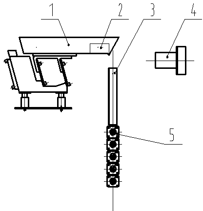
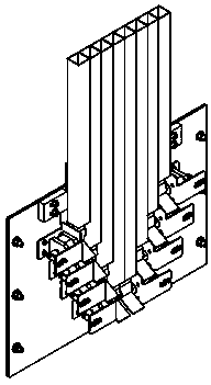
[0019] Below in conjunction with accompanying drawing, the present invention is further described: as figure 1 , figure 2 As shown, a channel-type color sorter sorting mechanism includes a vibrating feeding table 1, a material guide tube 3, a camera 4 and a paddle-type stepping motor sorting mechanism 5, and the outlet end of the vibrating feeding table 1 is provided with a Make the material fall into the passage dividing plate 2 corresponding to the material guiding pipe 3, the material guiding pipe 3 is located directly below the outlet end of the vibrating feeding table 1, and the shooting range of the camera 4 is between the vibrating feeding table 1 and the material guiding pipe 3 . The camera 4 is connected with the image signal processing control system, and the pictures taken are input into the control system, and after the judgment, the movement of the plectrum is controlled to achieve the purpose of sorting.

[0020] The paddle-type stepping motor sorting mechanis...


PUM


Abstract

The invention provides a channel type sorting mechanism of a color selector and a sorting method. The channel type sorting mechanism of the color selector comprises a vibration feeding platform (1), material guiding tubes (3), a camera (4) and a shifting sheet type stepping motor sorting mechanism body (5). The outlet end of the vibration feeding platform (1) is provided with channel partition plates (2) used for enabling materials to fall into the corresponding material guiding tubes (3). Each material guiding tube (3) is located under the outlet end of the vibration feeding platform (1). The shooting range of the camera (4) is located between the vibration feeding platform (1) and the material guiding tubes (3). The camera (4) is connected with an image signal processing control system. The channel type sorting mechanism of the color selector has the advantages that large-particle materials can be conveniently and reliably sorted in the process of sorting. Compared with a traditional air-pressure sorting mechanism, the channel type sorting mechanism of the color selector further has the advantages of being lower in energy consumption and cost, suitable for shell separation of various large-particle matters or sorting and classification of different particle matters, simple in installation and debugging process, and capable of avoiding redundant design of the color selector.

Description

technical field [0001] The invention relates to the technical field of color sorters, in particular to a channel-type color sorter sorting mechanism and method. Background technique [0002] The color sorter is a kind of use of different optical properties of different materials to detect and separate a variety of materials or to sort and grade the same material. [0003] The application number is 201120567055.2, and the utility model patent titled "a camellia oleifera shelling and sorting machine" involves a traditional mechanical sorting mechanism, which has low precision compared to optical-assisted sorting. Low adjustability. [0004] The application number is 201120470671.6, and the name is a utility model patent named "a matrix nozzle actuator for a color sorter". The matrix nozzle sorting mechanism introduced adopts a combined electrical sorting method. Noisy. [0005] The application number is 94110969.0, and the invention patent application named "Rice Electrosta...

Claims


Application Information

Patent Timeline
Patent Type & Authority Applications(China)
IPC IPC(8): B07C5/342B07C5/36
Inventor 王焱清周敬东周明刚陈源冯天玉谢柏林黄云朋刘浩
Owner HUBEI UNIV OF TECH
Learn More