Electro-hydraulic drive M-shaped steel ladle capping and decapping device

A technology of uncovering device and section steel, which is applied in metal processing equipment, casting melt container, casting equipment, etc., can solve the problem that the ladle capping operation is far from achieving the effect of energy saving and environmental protection of steel smelters, has not been effectively controlled, and can be Operability restrictions and other issues, to achieve the effect of increasing the free pouring rate, reducing mechanical damage, and reducing the need for cleaning

Inactive Publication Date: 2013-12-25
JIANGSU DISA MACHINERY
View PDF8 Cites 5 Cited by
  • Summary
  • Abstract
  • Description
  • Claims
  • Application Information

AI Technical Summary

Problems solved by technology

In order to solve the second part of the problem of "radiant heat dissipated to the air through the top opening of the ladle", some iron and steel enterprises have already started the ladle capping operation on the continuous casting machine. However, because the existing ladle capping operation must be completed with the assistance of the crane , so that the operability of this technology in practical applications is greatly limited, so that most of this technology is only used in the stage of continuous casting and pouring steel, and it is impossible to keep the ladle covered during the entire cycle of the ladle. Covering the ladle for heat preservation will result in a serious loss of temperature during the entire recycl

Method used


Image

  • Electro-hydraulic drive M-shaped steel ladle capping and decapping device
  • Electro-hydraulic drive M-shaped steel ladle capping and decapping device
  • Electro-hydraulic drive M-shaped steel ladle capping and decapping device

Examples


Embodiment Construction

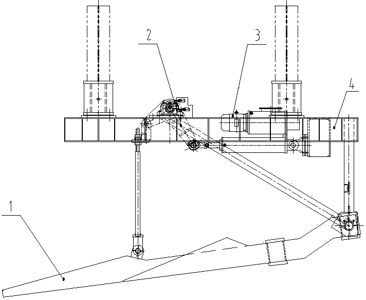
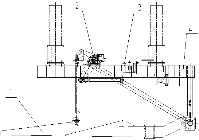
[0020] Such as figure 1 , 2 As shown, it is an electro-hydraulic M-type ladle capping and uncovering device, including a fixed frame 4, on which the electro-hydraulic push rod 3 and the linkage mechanism 2 are fixedly connected, and on the fixed frame 4, the M-type fork tine assembly is hinged. 1, the electro-hydraulic push rod 3 is connected to the link mechanism 2, and the link mechanism 2 is hingedly connected to the M-type fork assembly 1.

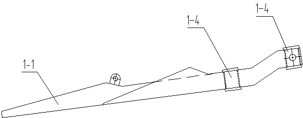
[0021] Such as image 3 , 4 As shown, the M-type fork tooth assembly 1 includes two long slope racks 1-1 and a short slope rack 1-2, and the short slope rack 1-2 is arranged between the two long slope racks 1-1 Two long slope racks 1-1 and one short slope rack 1-2 are fixed by welding two box girders 1-4, one of the two box girders 1-4 is one box girder 1- 4 and each long slope rack 1-1 and short slope rack 1-2 are respectively fixed by channel steel 1-3 welding.

[0022] Such as Figure 5 , 6 As shown, when the ladle 6 with the...


PUM


Abstract

The invention discloses an electro-hydraulic drive M-shaped steel ladle capping and decapping device, which relates to the structure of a whole-course full-automatic capping and decapping device of a high-temperature melt container in metal smelting. The electro-hydraulic drive M-type steel ladle capping and decapping device comprises a fixed frame, wherein the fixed frame is fixedly connected with an electro-hydraulic push rod and a connecting rod mechanism; the fixed frame is hinged to an M-shaped prong assembly; the electro-hydraulic push rod is connected with the connecting rod mechanism; the connecting rod mechanism is hinged to the M-shaped prong assembly. According to the electro-hydraulic drive M-type steel ladle capping and decapping device disclosed by the invention, the electro-hydraulic push rod is stretched to drive the connecting rod mechanism to control the swinging of the M-shaped prong assembly, an included angle between the M-shaped prong assembly and the horizontal plane is regulated, and capping and decapping are realized by the movement of a buggy ladle. High-cost heat energy is avoided and prevented from outwards losing to the outside from a steel ladle lining used for containing molten steel and liquid steel, the steel mill production cost is lowered, the operation condition is improved, and the production rate is improved.

Description

technical field [0001] The invention relates to the structure of a full-automatic capping and uncovering device for high-temperature melt containers in metal smelting. Background technique [0002] Energy saving and emission reduction has become the country's overall strategic goal, and iron and steel enterprises are big energy consumers. At present, the path of heat energy loss during the use of the ladle is generally composed of two parts, one is the conduction heat between the lining and the cladding, and the other is the radiant heat dissipated to the air through the opening at the top of the ladle. In order to solve the second part of the problem of "radiant heat dissipated to the air through the top opening of the ladle", some iron and steel enterprises have already started the ladle capping operation on the continuous casting machine. However, because the existing ladle capping operation must be completed with the assistance of the crane , so that the operability of ...

Claims


Application Information

Patent Timeline
IPC IPC(8): B22D41/00
Inventor 戴汝山
Owner JIANGSU DISA MACHINERY
Why Eureka
Try Eureka