Three-dimensional numerical control electric spark linear cutting machine tool

A technology of wire electric discharge and cutting machine tools, which is applied in the field of CNC wire cutting machine tools, can solve problems such as three-dimensional modeling, complicated programming, large accumulative errors in clamping, and complicated workpieces in clamping, so as to reduce quality management costs and reduce defective products , The effect of low machine maintenance cost

Active Publication Date: 2013-12-25
徐州博创建设发展集团有限公司
View PDF6 Cites 6 Cited by
  • Summary
  • Abstract
  • Description
  • Claims
  • Application Information

AI Technical Summary

Problems solved by technology

It can be summarized into two methods: a. Generally, the workpiece is clamped by rotating the workpiece multiple times, and then corrected; the limitations are: complicated proofreading, many human factors, low precision, and the difference in the intersection angle of the cutting surface of the finished product. Large accumulative errors in clamping
b. Using the fixture positioning method, the limitations are: proofreading the fixture, clamping the workpiece is complicated and the accumulated error is large, and the cost of the fixture is high
[0004] B. Use taper or large swing wire cutting machine tools, mechanical structure with more than four axes, and linkage system with more than four axes; the limitations are: it is difficult for workers to learn, difficult and slow to operate, and the price of the machine is high; it has not been popularized for a long time
However, the machining center has a lot of cutting material, complex mechanical structure, complex four-axis or more linkage system, three-dimensional modeling, complex programming, expensive labor, and high machine prices

Method used


Image

  • Three-dimensional numerical control electric spark linear cutting machine tool
  • Three-dimensional numerical control electric spark linear cutting machine tool
  • Three-dimensional numerical control electric spark linear cutting machine tool

Examples


Embodiment Construction

[0034] The embodiments of the present invention will be described in detail below with reference to the accompanying drawings, but the present invention can be implemented in many different ways defined and covered by the claims.

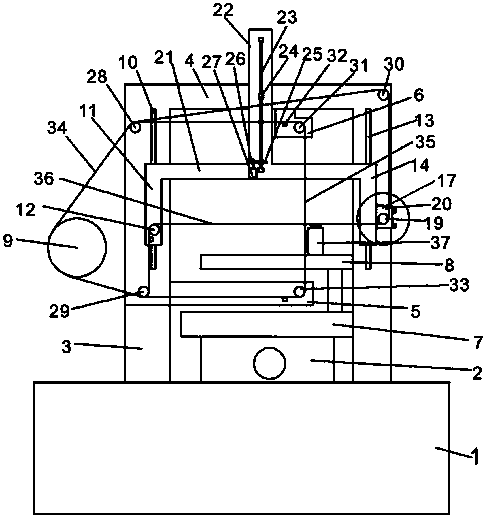
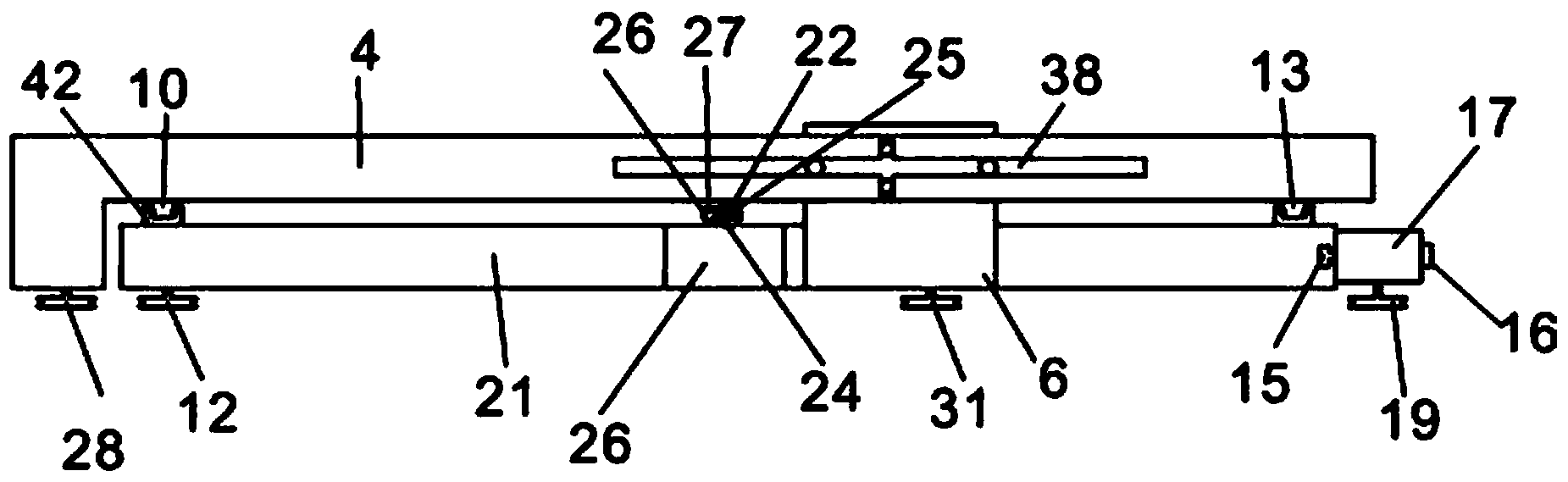
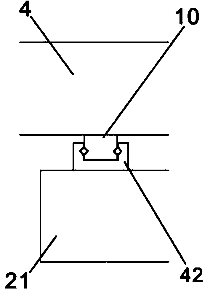
[0035] refer to Figure 1 to Figure 4 ,like figure 1 , figure 2 and image 3 A three-dimensional numerically controlled wire-cut electric discharge machine tool shown includes a bed 1, a cross slide 2 arranged on the bed 1, and left and right columns 3 fixed on the bed 1, and the left and right columns 3 The upper part is provided with a crossbeam 4 connecting the columns 3 on the left and right sides, the middle part of the left column 3 is provided with a lower wire arm 5, and the middle part of the crossbeam 4 is provided with an upper wire arm 6, a moving guide rail 38 and a screw pair 24. The upper wire arm 6 is slidably installed on the moving guide rail 38; the cross carriage 2 is provided with a working table 7, and the working table 7 i...


PUM


Abstract

The invention discloses a three-dimensional numerical control electric spark linear cutting machine tool comprising a machine tool body, a cross saddle which is arranged on the machine tool body, and vertical columns which are fixedly arranged on the left side and the right side of the machine tool body; crossbeams which are connected with the vertical columns on the left side and the right side are arranged at the upper parts of the vertical columns; a left linear arm guide rail is arranged on the vertical column on the left side; a left linear arm is arranged on the left linear arm guide rail; the lower end of the left linear arm is provided with a left guide pulley; a right linear arm guide rail is arranged on the vertical column on the right side; a right linear arm is arranged on the right linear arm guide rail; the lower end of the right linear arm is provided with a right guide pulley; the upper end of the left linear arm is connected with the upper end of the right linear arm through a cross arm; the cross arm is provided with a z-axis lead screw; the z-axis lead screw is movably connected onto a lead screw pair. According to the three-dimensional numerical control electric spark linear cutting machine tool, the structure is simple, three guide pulleys and a group of z saddle are added based on an original common linear cutting machine tool, the winding path of an electrode wire is changed, i.e. the one-time clamping of a work piece is realized, the cutting of a three-dimensional surface is realized, and the machine tool is low in cost, easily used and easily promoted.

Description

technical field [0001] The invention relates to a numerical control wire cutting machine tool, in particular to a three-dimensional numerical control wire cutting machine. Background technique [0002] Today, the cutting method of three-dimensional solid surface using wire electric discharge machine: [0003] A. Use ordinary wire cutting machine tools, rotate the workpiece or fixture, and cut after cumbersome proofreading. It can be summarized as two methods: a. Generally, the workpiece is clamped by rotating the workpiece multiple times, and then corrected; the limitations are: complicated proofreading, many human factors, low precision, and the intersection angle of the cut surface of the finished product is different each time. The accumulative error of clamping is large. b. Using the fixture positioning method, the limitations are: proofreading the fixture, clamping the workpiece is complicated and the accumulated error is large, and the cost of the fixture is high. ...

Claims


Application Information

Patent Timeline
Patent Type & Authority Applications(China)
IPC IPC(8): B23H7/02
Inventor 沈昌余
Owner 徐州博创建设发展集团有限公司
Why Eureka
Try Eureka