Thin-wall motor case milling fixture

A motor shell, thin-walled technology, used in clamping, manufacturing tools, metal processing mechanical parts, etc., can solve the problems of low production efficiency, slow processing speed, and difficult to operate, and achieve high production efficiency, high manufacturing precision, The effect of convenient workpiece clamping

Active Publication Date: 2013-12-25
芜湖杰诺瑞汽车电器系统有限公司
View PDF8 Cites 10 Cited by
  • Summary
  • Abstract
  • Description
  • Claims
  • Application Information

AI Technical Summary

Problems solved by technology

Usually, the outer circle is used as the positioning and installation reference for milling grooves of thin-walled motor casings, and manual clamping is mostly used. The disadvantages are: easy to produce clamping deformation, low production efficiency, slow processing speed, and difficult to operate

Method used


Image

  • Thin-wall motor case milling fixture
  • Thin-wall motor case milling fixture
  • Thin-wall motor case milling fixture

Examples


Embodiment 1

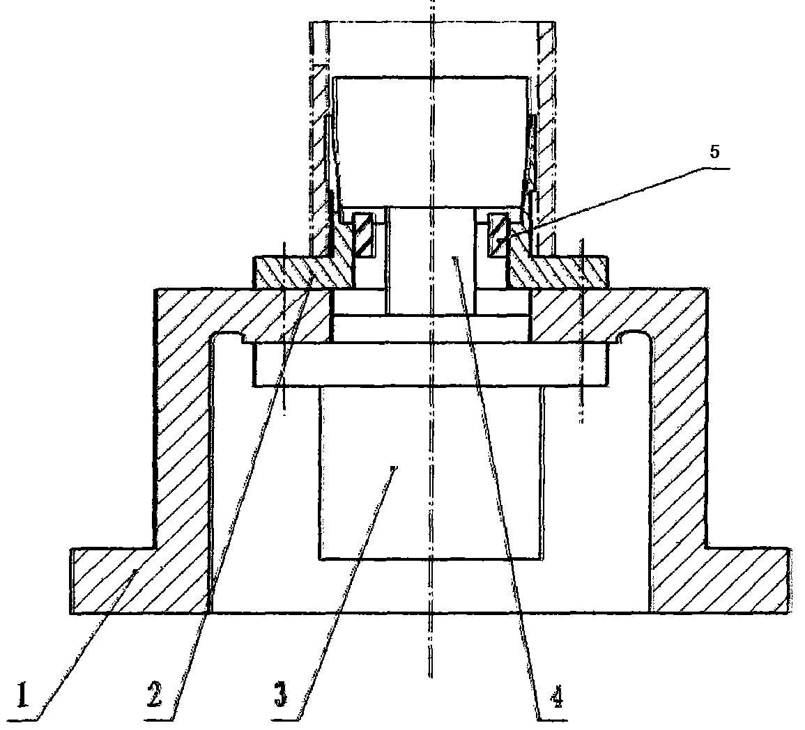
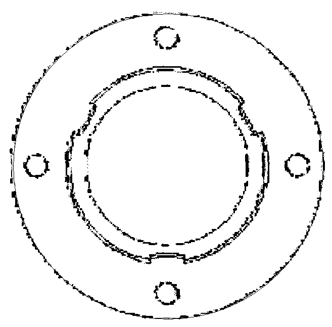
[0031] A thin-wall motor casing milling fixture is composed of a clamp body 1, an elastic thin-wall sleeve 2, a cylinder 3 and a clamping block 4. There are three grooves on the circumferential wall of the elastic thin-walled sleeve 2 to ensure the elasticity of the clamp body. The inner hole is designed to be tapered and installed on the clamp body 1 with screws; The outer circular surface of block 4 is designed to be tapered to match the tapered shape of the inner hole of the circumferential wall of elastic thin-walled sleeve 2, and the clamping block is enclosed within the elastic thin-walled sleeve. The workpiece is put into the elastic sleeve at the front end of the elastic thin-walled sleeve 2, and the cylinder 3 moves downward to drive the clamping block 4 to move axially. The elastic sleeve expands outwards, thereby clamping the workpiece, avoiding clamping deformation and fast clamping speed; after processing, the cylinder moves upwards, causing the elastic thin-walle...

Embodiment 2

[0033] A thin-wall motor shell milling fixture is composed of a clamp body 1, an elastic thin-wall sleeve 2, a cylinder 3, a clamping block 4 and a protective baffle 5. By selecting protective baffles 5 of different heights, the downward movement threshold value of the clamping block 4 can be set. When the clamping piece 4 moves downwards, it touches the protective baffle 5 and stops moving downwards, thereby avoiding acceleration during the clamping process. Excessive pressure produces shell deformation. The protective baffle 5 is a complete sleeve or consists of at least one separate sub-baffle. Using several separate baffles, compared with a complete sleeve, can save materials.

[0034] The connection mode between the protective baffle 5 and the side of the elastic thin-walled sleeve 2 according to the present invention is a flexible connection, sub-baffles with different heights can be selected, and can be flexibly selected for thin-walled motor casings of different mater...

Embodiment 3

[0037] A thin-wall motor shell milling fixture is composed of a clamp body 1, an elastic thin-wall sleeve 2, a cylinder 3, a clamping block 4 and a protective baffle 5. By selecting protective baffles 5 of different heights, the downward movement threshold value of the clamping block 4 can be set. When the clamping piece 4 moves downwards, it touches the protective baffle 5 and stops moving downwards, thereby avoiding acceleration during the clamping process. Excessive pressure produces shell deformation.

[0038] The inner hole of the elastic thin-walled sleeve 2 of the present invention is tapered. It can ensure that the clamping is more reliable to the greatest extent possible.

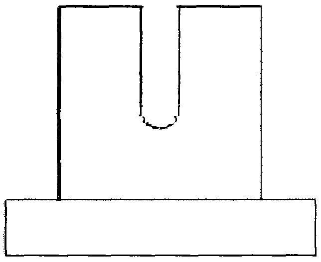
[0039] At least one groove is formed on the circumferential wall of the elastic thin-walled sleeve 2 of the present invention. Three grooves can be arranged on the circumferential wall of the elastic thin-walled sleeve 2 of the present invention. The material cost of the elastic thin-walled slee...


PUM


Abstract

The invention relates to the field of motor machining, in particular to a thin-wall motor case milling fixture, aiming at realizing the goals that the requirements on positioning and clamping reliability and production efficiency are met, the accuracy is guaranteed, the clamping force is uniform, machined surfaces are not damaged, the production cost is decreased and the situation of case deformation caused by excessive pressing during clamping is avoided. In order to realize the goals, the technical scheme adopted by the invention is that the thin-wall motor case milling fixture comprises a fixture body, an elastic thin wall sleeve and a clamping block, the elastic thin wall sleeve is installed on the fixture body, the outer surface of the clamping block is conical and the thin-wall motor case milling fixture additionally comprises a device which is installed below the fixture body and can control the fixture body to move back and forth.

Description

technical field [0001] The invention relates to the field of motor processing, in particular to a thin-walled motor casing milling fixture. Background technique [0002] In the field of mechanical processing, many workpieces, such as the motor housing involved in the present invention, especially the thin-walled motor housing, require special fixtures when tooling, so that tooling can be carried out effectively, so that the next step of processing is carried out. Usually, the outer circle is used as the positioning and installation reference for milling grooves of thin-walled motor casings, and manual clamping is mostly used. The disadvantages are: easy to produce clamping deformation, low production efficiency, slow processing speed, and difficult to operate . Contents of the invention [0003] The problem to be solved by the present invention is to provide a milling fixture for a thin-walled motor casing, the purpose of which is to meet the requirements of positioning, ...

Claims


Application Information

Patent Timeline
Patent Type & Authority Applications(China)
IPC IPC(8): B23Q3/08B23Q3/06
Inventor 许其山曾庆平
Owner 芜湖杰诺瑞汽车电器系统有限公司
Why Eureka
Try Eureka