Mechanical lifting device for fluorescent lamp tubes

A technology for mechanical lifting and fluorescent lamps, which is applied to manipulators, program-controlled manipulators, and the manufacture of discharge tubes/lamps. Effect

Inactive Publication Date: 2015-04-22
荆州市大明灯业有限公司
View PDF7 Cites 0 Cited by
  • Summary
  • Abstract
  • Description
  • Claims
  • Application Information

AI Technical Summary

Problems solved by technology

[0002] At present, in the manufacturing process of fluorescent lamp tubes, the product transfer between various production links on the production line is completed by manipulators. Due to the poor versatility of the production line and the diversity of fluorescent lamp tube specifications, some small or super Due to the short length and a certain distance from the normal grabbing point of the manipulator during the production process, the small fluorescent lamp tube cannot be normally grasped by the manipulator, so that the normal production of the fluorescent lamp tube production line cannot be performed, and the small or ultra-small fluorescent lamp tube cannot be grasped by the manipulator. Normal transmission between various production links of the production line; seriously affecting the normal production of small or ultra-small fluorescent lamp tubes

Method used


Image

  • Mechanical lifting device for fluorescent lamp tubes
  • Mechanical lifting device for fluorescent lamp tubes

Examples


Embodiment Construction

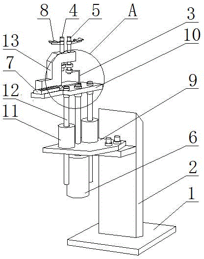
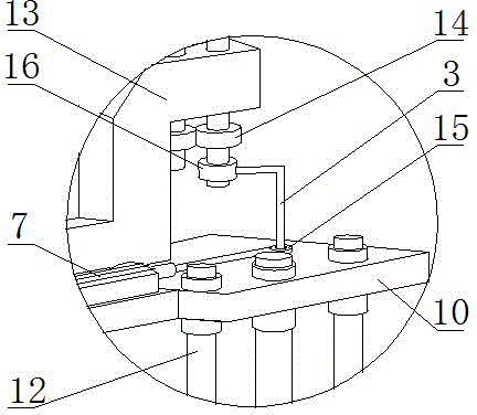
[0011] The mechanical lifting device for fluorescent lamp tubes consists of a base 1, a support arm 2, a crank connecting rod 3, a rotating shaft A4, a rotating shaft B5, a lifting cylinder 6, a rotating cylinder 7 and jaws 8. The support arm 2 is welded on the base 1, and the support arm 2 is fixedly equipped with an installation base plate 9. The lifting cylinder 6 is installed on the lower surface of the installation base plate 9, and the piston rod of the lifting cylinder 6 extends to the installation base plate 9. The end of the piston rod The head is fixedly equipped with a top plate 10 for installation.

[0012] Linear bearings 11 are installed symmetrically on both sides of the piston rod on the upper surface of the bottom plate 9, and guide rods 12 are installed symmetrically on both sides of the piston rod on the lower surface of the top plate 10, and the guide rods 12 are slidably connected with the linear bearings 11.

[0013] The upper surface of the installation ...


PUM


Abstract

The invention relates to a mechanical lifting device, in particular to a mechanical lifting device for fluorescent lamp tubes. The mechanical lifting device is formed by a base, a supporting arm, a crank connecting rod, a rotating shaft A, a rotating shaft B, a lifting air cylinder, a rotating air cylinder and clamping jaws, wherein the supporting arm is fixedly provided with an installation bottom plate, the lower surface of the installation bottom plate is provided with the lifting air cylinder, the end head of a piston rod of the lifting air cylinder is fixedly provided with an installation top plate, and the installation top plate is provided with the rotating shaft A and the rotating shaft B. According to the mechanical lifting device disclosed by the invention, the lifting air cylinder and the rotating air cylinder are sequentially controlled to move through a program control box, the position lifting of small-sized or ultra-small fluorescent lamp tubes in a production line can be completed, and the problem that small-sized or ultra-small fluorescent lamp tubes in an existing production line cannot be normally grabbed by a mechanical hand as the lengths of the small-sized or ultra-small fluorescent lamp tubes are short is solved; the grabbing requirements of the mechanical hand can be met when various types of small-sized or ultra-small fluorescent lamp tubes are produced, and the mechanical lifting device is particularly suitable for being used for position lifting of the small-sized or ultra-small fluorescent lamp tubes in the production line.

Description

technical field [0001] The invention relates to a mechanical lifting device, in particular to a mechanical lifting device for fluorescent lamp tubes. Background technique [0002] At present, in the manufacturing process of fluorescent lamp tubes, the product transfer between various production links on the production line is completed by manipulators. Due to the poor versatility of the production line and the diversity of fluorescent lamp tube specifications, some small or super Due to the short length and a certain distance from the normal grabbing point of the manipulator during the production process, the small fluorescent lamp tube cannot be normally grasped by the manipulator, so that the normal production of the fluorescent lamp tube production line cannot be performed, and the small or ultra-small fluorescent lamp tube cannot be grasped by the manipulator. It is normally transmitted between the various production links of the production line; it seriously affects the...

Claims


Application Information

Patent Timeline
Patent Type & Authority Patents(China)
IPC IPC(8): B25J9/04B25J9/10H01J9/00
Inventor 胡新洪杨焕清朱洪元池昌明倪功大
Owner 荆州市大明灯业有限公司
Why Eureka
Try Eureka