Electric sanitation vehicle chassis and electric sanitation vehicle with same

A sanitation vehicle and electric technology, which is applied to electric power units, power units, vehicle components, etc., can solve the problems of short cruising range and operating time, easy water entry of power batteries, and inconvenient maintenance of power batteries, so as to increase the cruising range. and working time, strong accidents and natural disasters, good ventilation and heat dissipation performance

Active Publication Date: 2013-12-25
ZOOMLION ENVIRONMENTAL IND CO LTD
View PDF6 Cites 12 Cited by
  • Summary
  • Abstract
  • Description
  • Claims
  • Application Information

AI Technical Summary

Problems solved by technology

However, the arrangement of the above-mentioned motor and power battery in the chassis of the existing electric vehicle results in a small ground clearance of the chassis, poor vehicle passability, and the drive motor and power battery are easily hit by protruding foreign objects on the road surface. It is easy to enter water, which poses a great safety hazard; secondly, the drive motor is located on the rear axle, and the power battery is located under the frame frame of the chassis, which is not convenient for maintenance of the power battery; in addition, due to the small installation space under the chassis, the power battery The capacity is small, the cruising range and operation time of the vehicle are short, it is difficult to meet the long-term operation, the rated power and torque of the drive motor are also small, and the power performance and climbing characteristics are poor
Therefore, it is not enough to design electric vehicles from the existing design concept of traditional fuel vehicles

Method used


Image

  • Electric sanitation vehicle chassis and electric sanitation vehicle with same
  • Electric sanitation vehicle chassis and electric sanitation vehicle with same
  • Electric sanitation vehicle chassis and electric sanitation vehicle with same

Examples


Embodiment Construction

[0031] In order to describe the technical content, structural features, achieved goals and effects of the present invention in detail, the following will be described in detail in conjunction with the embodiments and accompanying drawings.

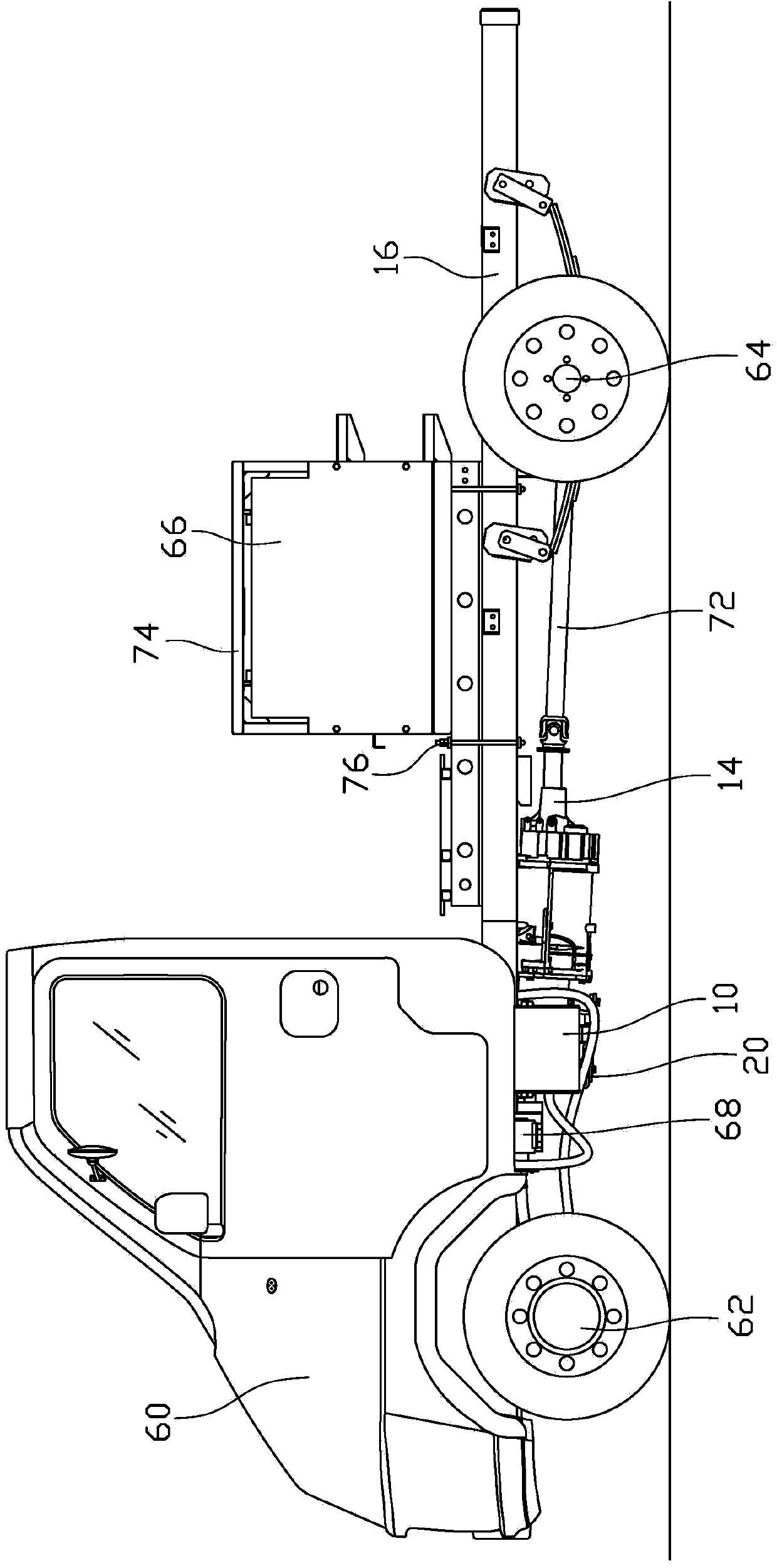
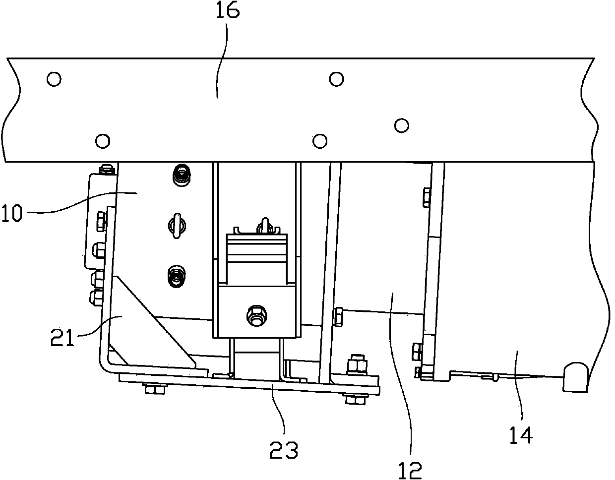
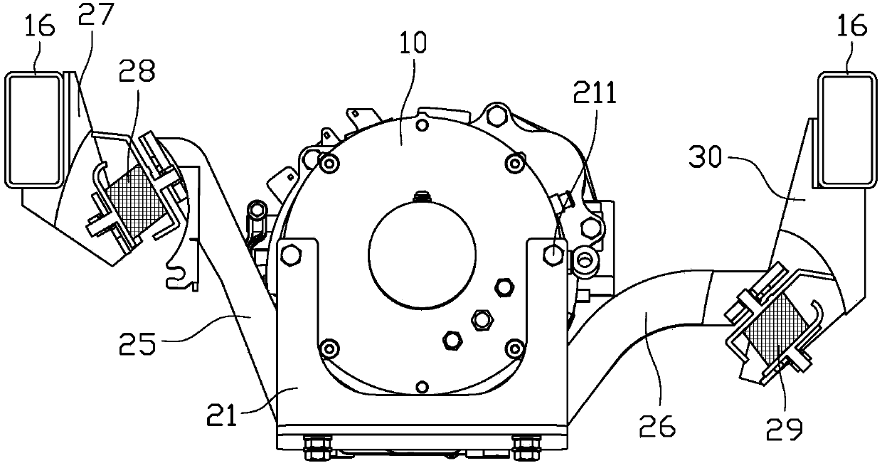
[0032] see figure 1 , the present invention discloses an electric sanitation vehicle chassis, which includes a cab 60, a front axle 62, a rear axle 64, a drive shaft 72, a drive motor 10, a clutch gearbox 14 and a vehicle frame (not shown). The frame includes longitudinal beams 16 . The clutch gearbox 14 is fixed on the vehicle frame. The driving motor 10 is arranged under the cab 60 . The drive motor 10 is connected to the clutch gearbox 14, and the two ends of the transmission shaft 72 are respectively connected to the clutch gearbox 14 and the rear axle 64, so as to transmit the power to the rear axle and realize the motor front and rear drive. Since the drive motor 10 is arranged under the driver's cab 60, the drive motor 10 has a l...


PUM


Abstract

The invention provides an electric sanitation vehicle chassis which comprises a cab, a front axle, a rear axle, a transmission shaft, a drive motor, a power battery, a clutch gearbox and a frame. The frame comprises a longitudinal beam. The drive motor is disposed below the cab and located behind the front axle. The power battery is mounted on the longitudinal beam and located between the front axle and the rear axle. The drive motor is connected with the clutch gearbox. Two ends of the transmission shaft are respectively connected with the clutch gearbox and the rear axle. The invention further provides an electric sanitation vehicle with the electric sanitation vehicle chassis. The electric sanitation vehicle chassis and the electric sanitation vehicle with the same has the advantages that the drive motor is disposed below the cab and located behind the rear axle, the power battery is mounted above the frame of the chassis and located between the front axle and the rear axle, the motor is disposed in the front and driven at the rear, stable chassis performance is achieved, large gap away from the ground is achieved, and the power battery is convenient to assemble and maintain, and long the duration and operation time.

Description

technical field [0001] The invention relates to the field of electric vehicles, in particular to an electric sanitation vehicle and its chassis. Background technique [0002] As an environmentally friendly means of transportation, electric vehicles are more and more widely used. For example, in sanitation vehicles, electric road sweepers, electric garbage trucks, and electric road maintenance vehicles are more and more used. The existing traditional fuel-driven car chassis is heavy, mainly from the aspects of adhesion, handling, compactness of the transmission mechanism, impact on space, and load distribution. The engine is front-rear drive, rear-rear drive, front Front-wheel drive, center-mounted rear-drive, or four-wheel drive. [0003] In the existing electric vehicle chassis, especially in the miniature pure electric chassis used for sanitation vehicles, the direct drive mode of the rear axle motor is adopted, and the power battery is installed at the bottom of the chas...

Claims


Application Information

Patent Timeline
Patent Type & Authority Applications(China)
IPC IPC(8): B60K1/00B60K1/04E01H1/08
Inventor 蒋亚萍肖庆麟李洲瞿球雄任永泰袁峰
Owner ZOOMLION ENVIRONMENTAL IND CO LTD
Why Eureka
Try Eureka