Floatation equipment

A kind of equipment and air flotation technology, applied in the direction of flotation water/sewage treatment, etc., can solve the problems of low water reuse standard, low removal rate, low noise, etc., to facilitate early installation and later maintenance, and improve air flotation effect , the effect of improving the efficiency of dissolved gas

Inactive Publication Date: 2013-12-25
常熟市新晨机械厂
View PDF10 Cites 6 Cited by
  • Summary
  • Abstract
  • Description
  • Claims
  • Application Information

AI Technical Summary

Problems solved by technology

[0002] Air flotation equipment is a kind of equipment that removes suspended solids, grease and various colloids in various industrial and municipal sewage. It is an indispensable equipment in sewage treatment. Generally, air flotation equipment is the separation of gas and liquid. For the solid-liquid separation effect is not obvious, the removal rate is not high, the application number is CN201020185969.8 discloses a kind of air flotation equipment, mainly including dissolved air pump, water inlet pipe, air inlet pipe, two positive pressure regulating valves, air-water separation tank, The air flotation mixing contact area, etc., the dissolved air pump is connected with the water inlet pipe and the air inlet pipe respectively, the air inlet pipe is connected with one side of the gas-water separation tank through a positive pressure regulating valve, and the other side of the gas-water separation tank is connected with the air-water separation tank through a pipeline. One end of another positive pressure regulating valve is connected, and the other end of the positive pressure regulating valve is connected with the air flotation mixing contact area. It is easy to operate and maintain, low in noise, and high in dissolved air flotation efficiency, but its efficiency in removing large particles is not high. Clear water Low recycling standard and high cost

Method used


Image

  • Floatation equipment

Examples


Embodiment Construction

[0011] In order to make the technical means, creative features, goals and effects achieved by the present invention easy to understand, the present invention will be further described below in conjunction with specific embodiments.

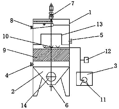
[0012] Such as figure 1 As shown, an air flotation device includes a cylinder body 1, a mud bucket 2 and an air-dissolving device 3, the cylinder body 1 is provided with a water inlet 4 and a water outlet 5, and the bottom of the cylinder body 1 is provided with a mud bucket 2, The mud hopper 2 is provided with a mud outlet 6, the top of the cylinder body 1 is provided with a skimming device 7 and a slag outlet 8, and the cylinder body 1 is provided with a sloping plate section 9, and the sloping plate section 9 is provided with Between the water inlet 4 and the water outlet 5, a micro-nano bubble generator 10 is arranged between the inclined plate section 9 and the water outlet 5, and the micro-nano bubble generator 10 is connected with the gas-...


PUM


Abstract

The invention discloses floatation equipment which relates to the field of mechanical equipment and comprises a barrel, a mud bucket and a gas dissolving device, wherein the barrel is provided with a water inlet and a water outlet, the mud bucket is arranged at the bottom of the barrel and is provided with a mud discharge hole, a drossing device and a slag hole are arranged on the top of the barrel, an inclined plate section is arranged in the barrel and is arranged between the water inlet and the water outlet, a micro-nano bubble generator is arranged between the inclined plate section and the water outlet and is connected with the gas dissolving device, and a micro-nano bubble generating device is arranged in the gas dissolving device. Due to the dual actions of an inclined plate and the gas dissolving device, large-particle flocculating constituents settle to form sludge, and small-particle flocculating constituents float on the water surface; clear water after dual solid-liquid separation is high in recycling standard; since the micro-nano bubble generator is utilized, not only is the gas dissolving efficiency improved, but also the adsorption effect can be realized on grease dirt and other substances, and the floatation effect is greatly improved.

Description

technical field [0001] The invention relates to the field of mechanical equipment, in particular to an air flotation equipment. Background technique [0002] Air flotation equipment is a kind of equipment that removes suspended solids, grease and various colloids in various industrial and municipal sewage. It is an indispensable equipment in sewage treatment. Generally, air flotation equipment is the separation of gas and liquid. For the solid-liquid separation effect is not obvious, the removal rate is not high, the application number is CN201020185969.8 discloses a kind of air flotation equipment, mainly including dissolved air pump, water inlet pipe, air inlet pipe, two positive pressure regulating valves, air-water separation tank, The air flotation mixing contact area, etc., the dissolved air pump is connected with the water inlet pipe and the air inlet pipe respectively, the air inlet pipe is connected with one side of the gas-water separation tank through a positive p...

Claims


Application Information

Patent Timeline
Patent Type & Authority Applications(China)
IPC IPC(8): C02F1/24
Inventor 张德生
Owner 常熟市新晨机械厂
Why Eureka
Try Eureka