Method for conducting grouting construction at back of pile bottom of cast-in-place pile

A construction method and post-grouting technology, which is applied to sheet pile walls, foundation structure engineering, construction, etc., can solve problems such as the difficulty of opening the grouting one-way valve, grouting failure, and blockage of the grouting injection head, so as to ensure the grouting Improve the pulp quality and success rate, increase the diffusion area, and prevent clogging

Active Publication Date: 2013-12-25
广东省第二建筑工程有限公司
View PDF5 Cites 10 Cited by
  • Summary
  • Abstract
  • Description
  • Claims
  • Application Information

AI Technical Summary

Problems solved by technology

[0004] However, since the grouting pipe and the steel cage are fixed together, it is easy to drive the grouting pipe to float up due to the floating of the steel cage, which affects the smooth progress of grouting and causes grouting failure; moreover, after the concrete pouring pile is piled, The outside of the grouting injection head is often cove

Method used


Image

  • Method for conducting grouting construction at back of pile bottom of cast-in-place pile
  • Method for conducting grouting construction at back of pile bottom of cast-in-place pile
  • Method for conducting grouting construction at back of pile bottom of cast-in-place pile

Examples


Example Embodiment

[0026] The grouting construction method at the bottom of this cast-in-situ pile includes the following steps in turn:

[0027] (1) Fabrication and placement of grouting pipes

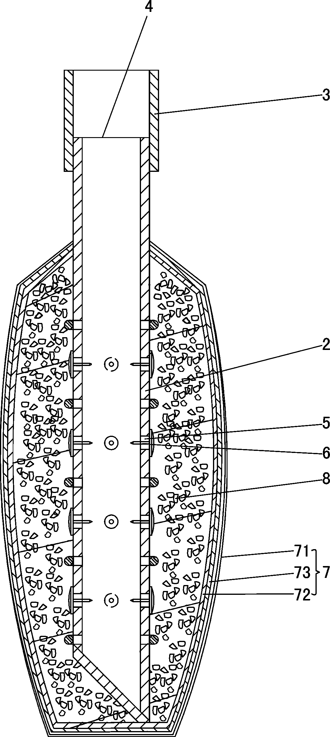
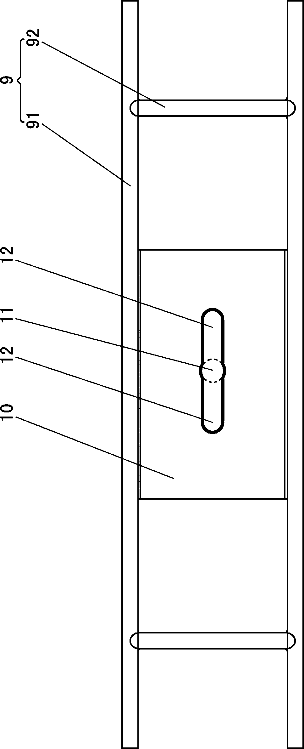
[0028] The grouting pipe includes multiple sections of grouting steel pipe sections connected sequentially from top to bottom, and the lower end of the lowest grouting steel pipe section is connected with a grouting injection head. refer to figure 1 and figure 2 , the grouting steel pipe section used includes a grouting pipe body 1, the grouting injection head used includes a grouting pipe body 2, the upper end of the grouting pipe body 1 is provided with a steel sleeve 3, and the upper end of the grouting pipe body 2 is also provided with a steel sleeve Sleeve 3, the inner edge of the cross section of the steel sleeve 3 matches the shape and size of the outer edge of the cross section of the grouting pipe body 1; A plurality of grouting holes 5 are arranged on the grouting hole 5, and a grouting ch...


PUM


Abstract

A method for conducting grouting construction at the back of the pile bottom of a cast-in-place pile sequentially includes the following steps: (1) manufacturing and arranging a grouting pipe which comprises a plurality of grouting steel pipe sections sequentially connected from top to bottom with the lower end of the lowest grouting steel pipe section connected with a grouting spraying nozzle; (2) assembling a grouting station and a slurry transportation pipeline; (3) grouting. The method is characterized in that the grouting spraying nozzle used in the step (1) comprises a slurry spraying pipe body, a slurry inlet is formed in the upper end of the slurry spraying pipe body, a plurality of slurry discharging holes are formed in the lateral wall of the slurry spraying pipe body, a grouting one-way valve is installed on the slurry discharging holes, a sand wrapping device is arranged on the outside of the slurry spraying pipe body, a sand isolation layer is arranged between the sand wrapping device and the outer side of the slurry spraying pipe body, and the sand isolation layer covers the grouting one-way valve. When the grouting spraying nozzle reaches the bottom of a pile hole, and the portion of the upper end of the grouting pipe higher than the ground reaches preset height, the upper end of the grouting pipe is fixedly connected with a protection barrel at the top of the pile hole. By means of the method, smooth grouting can be achieved, grouting quality is ensured, and success ratio is ensured.

Description

technical field [0001] The invention relates to a construction method for building foundation piles, in particular to a post-grouting construction method for pile bottoms of cast-in-place piles. Background technique [0002] Cast-in-situ piles have been widely used in construction projects because of their high bearing capacity and strong applicability, but the defects of cast-in-place piles will also cause insufficient bearing capacity of single piles due to certain reasons. Post-grouting technology is an auxiliary process for the construction of cast-in-place piles, which can effectively make up for the defects of cast-in-place piles and improve the bearing capacity of single piles. Post-grouting at the bottom of cast-in-place pile means: when the concrete of the pile body reaches a certain strength after the concrete pouring pile is formed, the cement slurry is injected into the bottom of the pile under pressure through the post-grouting equipment, and through the permeat...

Claims


Application Information

Patent Timeline
IPC IPC(8): E02D5/62
Inventor 林庆波陈清金林茂陈邻耀张柯生肖志坚丁斐斐
Owner 广东省第二建筑工程有限公司
Why Eureka
Try Eureka