
LED (light emitting diode) module and LED lamp manufactured by same

A technology for LED modules and LED lamps, which is applied to lighting and heating equipment, parts of lighting devices, semiconductor devices of light-emitting components, etc. The effect of utilization rate, increased uniformity, high light efficiency

Inactive Publication Date: 2013-12-25
OPTOTECH SUZHOU
View PDF5 Cites 1 Cited by
  • Summary
  • Abstract
  • Description
  • Claims
  • Application Information

AI Technical Summary

Problems solved by technology

[0003] The common problem of existing LED lamps is that the heat generated during the working process cannot be dissipated in time, which is easy to cause heat accumulation, and the large amount of heat generated during long-term work will easily lead to bad phenomena such as LED light decay and affect the life of the LED light.
Some LED lights are used outdoors. In rainy, windy and snowy weather, they are prone to water and moisture. The circuit boards in the LED lights are prone to short circuits due to water vapor, causing LED lights to burn out, etc.
[0004] Moreover, for traditional LED lamps, all the LED lamp beads on it are arranged on a large flat-shaped LED circuit board. These LED lamp beads can only be on the same plane, and the light emitted by each lamp bead Large-scale overlapping occurs in the air, so that in the target lighting area, some places will be very dark because only a small part of the light is shining, and some places will be very bright because a lot of light is shining. As a result, very obvious light spots appear in the target lighting area, and the illumination uniformity is very poor
In this way, it is necessary to use enough LED lamp beads and enough luminous power to make every place in the target lighting area obtain the required light intensity, which consumes a lot of power.

Method used


Image

  • LED (light emitting diode) module and LED lamp manufactured by same
  • LED (light emitting diode) module and LED lamp manufactured by same
  • LED (light emitting diode) module and LED lamp manufactured by same

Examples


Embodiment 1

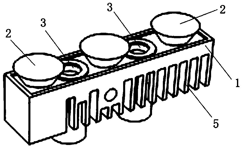
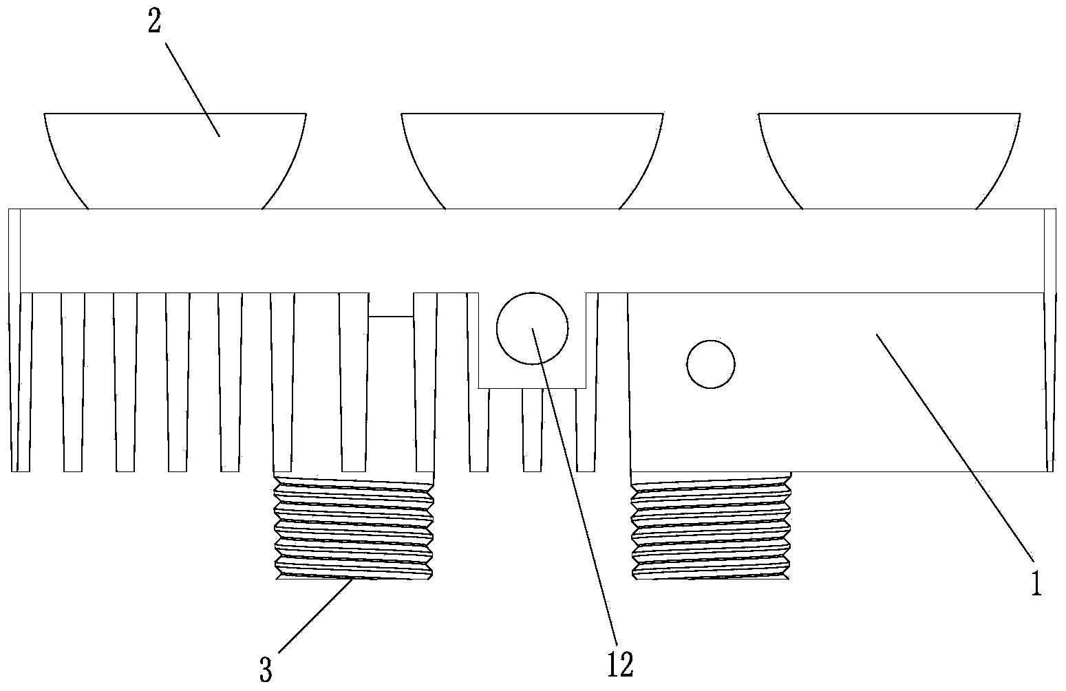
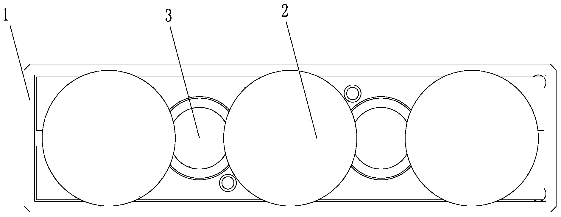
[0037] Such as Figure 1 ~ Figure 4 As shown, the LED module provided by this embodiment is very light and small in size, and it includes a base 1, an LED circuit board (not shown in the figure) fixed on the base, and a LED circuit board located on the base. The 3 LED lamp beads (not shown in the figure), these 3 LED lamp beads are distributed in a straight line on the LED circuit board, and each LED lamp bead is covered with a fixed on the LED circuit board Lens 2 on top. Moreover, several heat dissipation fins 5 and two air convection cooling holes 3 passing through the base are formed on the base 1 to ensure that the LED module has good heat dissipation performance, and the base in this implementation 1 Made of aluminum material with good heat dissipation.

[0038] In this embodiment, the outer contour of the base 1 is in the shape of a cuboid, such as figure 1 .

[0039] In this embodiment, the light emitting angles of all the lenses 2 fixed on the LED circuit board ca...

Embodiment 2

[0051] Such as Figure 9 ~ Figure 12 As shown, the structure of the LED module provided in this embodiment is similar to that of Embodiment 1, the main differences are:

[0052] a. In this example, the outer contour of the base 1 is in the shape of a regular hexagonal prism, on which 6 air convection cooling holes 3 penetrating the base are formed, and these 6 air convection cooling holes 3 are respectively arranged on the regular hexagonal prism on the six sides of the shape.

[0053] b. There are 6 LED lamp beads (not shown in the figure) on the LED circuit board, and the 6 LED lamp beads are distributed in a regular hexagon on the LED circuit board.

[0054] c. In this example, the base 1 is not provided with external threads surrounding the air convection cooling holes 3 , but a threaded hole 4 is formed at the center of the bottom of the base 1 . The purpose of this design is the same as the external thread surrounding the air convection cooling hole 3 in the first embo...


PUM


Abstract

The invention discloses an LED (light emitting diode) module and an LED lamp manufactured by the LED module. The LED module comprises a base, an LED circuit board fixed on the base and 1-8 LED lamp beads positioned on the LED circuit board; each LED lamp bead is covered by a lens fixed on the LED circuit board; a plurality of radiating fins and at least one air convection radiating hole penetrating through the base are molded on the base; the LED lamp comprises a non-plane module mounting plate; a plurality of the LED modules distributed in all three-dimensional directions are fixed on the module mounting plate. The LED lamp disclosed by the invention has higher light ray utilization rate, the lighting uniformity is greatly increased, the light energy of an LED light source can be fully utilized, the light efficiency is high, power needed for the lighting demand is small and energy-saving and environment-friendly requirements are realized.

Description

technical field [0001] The invention relates to an LED module and an LED lamp made of the LED module, belonging to the field of lighting equipment. Background technique [0002] Functional lighting tools such as street lights and tunnel lights require that the illuminance of each point within the lighting range must meet the minimum illuminance index, the highest glare requirement index, the light intensity uniformity index and the illumination area limit requirements required by the lighting specification, which is very important for the reliability of the product. The requirements for safety, energy saving and environmental performance are also very high. Existing street lamps and tunnel lamps generally have poor uniformity of illuminance irradiating the ground. In order to improve the lighting effect and protect the health of human eyes, it is necessary to use lamps to carry out optical system lighting distribution, that is, in a designated road position and a given road...

Claims


Application Information

Patent Timeline
Patent Type & Authority Applications(China)
IPC IPC(8): F21S2/00F21V29/00F21V31/00F21V5/04F21V17/10F21V17/12F21Y101/02F21V29/74F21V29/83
CPCF21K9/00F21W2131/103F21V29/763F21V29/773F21V29/83F21K9/60F21Y2115/10F21Y2103/33F21Y2107/20F21V5/04
Inventor 庄俊尧
Owner OPTOTECH SUZHOU
Learn More