Energy-saving catalytic bed system

A catalytic bed, energy-saving technology, applied in the field of catalytic beds, can solve the problems of reduced catalyst efficiency, poor self-compensation feedback effect, and increased operating energy consumption, so as to improve combustion efficiency and purification rate, uniform temperature compensation, and overcome high temperature Effect

Inactive Publication Date: 2015-07-22
赛智环保科技(天津)有限公司
View PDF7 Cites 0 Cited by
  • Summary
  • Abstract
  • Description
  • Claims
  • Application Information

AI Technical Summary

Problems solved by technology

The existing catalytic bed has the following problems: 1. Due to the uniformity of gas distribution and VOCs concentration, the temperature in different areas of the bed is not uniform, and the overall central temperature is higher than that of the surrounding area, and dead zones are prone to appear in the four corners of the square furnace
2. The self-compensation feedback effect of the catalytic combustion exothermic process on the temperature in the furnace is poor, so that the air blowing effect on the bottom of the bed is significant, and the inhomogeneity of the bed temperature is aggravated
As a result, the catalyst efficiency is reduced, the catalytic combustion purification rate is reduced, and the operating energy consumption is increased.

Method used


Image

  • Energy-saving catalytic bed system
  • Energy-saving catalytic bed system
  • Energy-saving catalytic bed system

Examples


Embodiment Construction

[0037] The present invention will be further described in detail below through the specific examples, the following examples are only descriptive, not restrictive, and cannot limit the protection scope of the present invention with this.

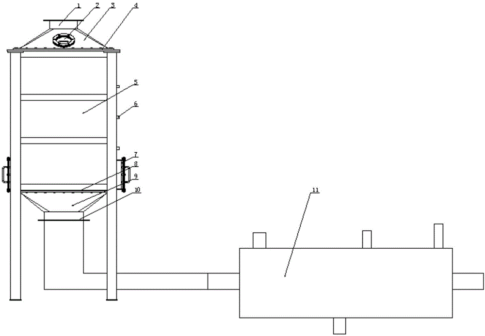
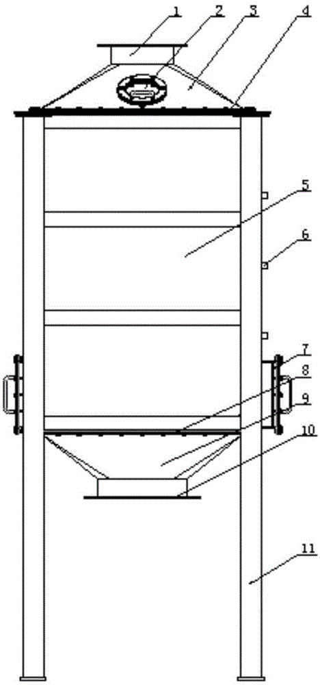
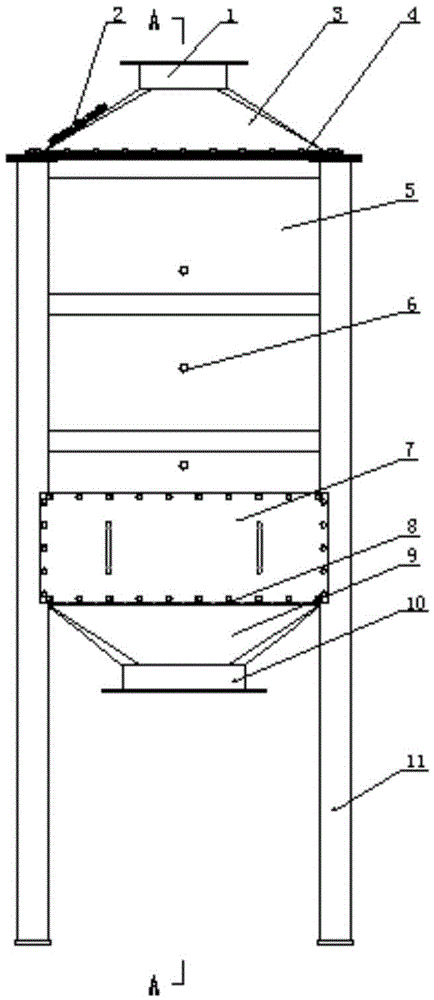
[0038]An energy-saving catalytic bed system, comprising an inlet hood 3, a furnace body 5, an outlet hood 9 and a heat exchanger 11, a support frame is arranged on the four corners of the outer wall of the furnace, an explosion-proof pressure relief port 2 is arranged on the inlet hood, and the furnace The upper end of the body is fixed with an air inlet hood, the lower end of the furnace body is fixed with an outlet hood, the upper end of the air inlet hood is provided with a gas inlet 1, and the lower end of the air outlet hood is provided with a gas outlet 10, and the furnace body includes a peripheral plate 22 of the furnace body and an upper end plate 4 fixed at its upper end and the lower end plate 8 fixed at its lower end, which is eve...


PUM


Abstract

The invention relates to an energy-saving catalytic bed system which comprises an air inlet cover, a furnace body, an air outlet cover and a heat exchanger; air inlet channels and air outlet channels are alternatively arranged between the inner coaming of the furnace body and the outer coaming of the furnace body; the inlet of each air inlet channel is arranged on an upper end plate, and the outlet of each air inlet channel is arranged between a lower end plate and the inner coaming of the furnace body; the inlet of each air outlet channel is arranged between the upper end plate and the inner coaming of the furnace body, and the outlet of each air outlet channel is arranged on the lower end plate; a heater is arranged in the furnace body which corresponds to the outlets of the air inlet channels; an air outlet deflection cover is arranged below the middle part of the lower end plate which corresponds to the outlet of the air outlet cover; the heat exchanger is provided with a catalytic exhaust inlet, a catalytic exhaust outlet, a catalytic gas inlet, a catalytic gas outlet, a desorption gas supply inlet and a desorption gas supply outlet. According to the energy-saving catalytic bed system, the heat efficiency of a catalytic bed is effectively improved, the heat loss is reduced, the heat recovery and utilization rate is improved, the burning efficiency and purification rate are improved, heat exchange is increased, the heat energy is utilized more reasonably, and the energy saving and emission reduction requirements are met.

Description

technical field [0001] The invention belongs to the field of catalytic beds, in particular to an energy-saving catalytic bed system. Background technique [0002] Industrial volatile organic pollutants in PM2.5 are one of the most harmful pollutants to people's health. At present, the mainstream process at home and abroad to control air pollution with large air volume and low concentration VOCs is: catalytic combustion after adsorption and concentration. The existing catalytic The enclosure structure of the bed furnace body is usually made of heat-resistant steel plate or industrial kiln masonry material, and the air inlet and outlet are set. The existing catalytic bed has the following problems: 1. Due to the uniformity of gas distribution and VOCs concentration, the temperature in different areas of the bed is not uniform, and the overall temperature in the center is higher than that in the surrounding area, and dead zones are prone to appear in the four corners of the squ...

Claims


Application Information

Patent Timeline
Patent Type & Authority Patents(China)
IPC IPC(8): F23G7/07
Inventor 朱殿兴刘光明冯正赵崇光谷德明刘迎春
Owner 赛智环保科技(天津)有限公司
Why Eureka
Try Eureka