Ultrasound vortex flowmeter

A vortex flowmeter and ultrasonic technology, applied in the field of flowmeters and flowmeters for measuring gas flow, can solve the problems of unstable square wave sequence frequency, affecting readings, affecting the ventilation quality and breathing safety of artificial ventilators, and achieving low pressure Loss, improve stability, improve real-time effects

Inactive Publication Date: 2013-12-25
HANGZHOU SHEZHANG TECH
View PDF7 Cites 4 Cited by
  • Summary
  • Abstract
  • Description
  • Claims
  • Application Information

AI Technical Summary

Problems solved by technology

Since the artificial respirator in the 1970s and 1980s did not have a flowmeter to measure the ventilation volume, this parameter was basically given based on the doctor's experience, which affected the ventilation quality and breathing safety of the artificial respirator.
The disadvantage of this flowmeter is that the frequency of the output square wave sequence is unstable, which affects the reading

Method used


Image

  • Ultrasound vortex flowmeter
  • Ultrasound vortex flowmeter
  • Ultrasound vortex flowmeter

Examples


Embodiment 1

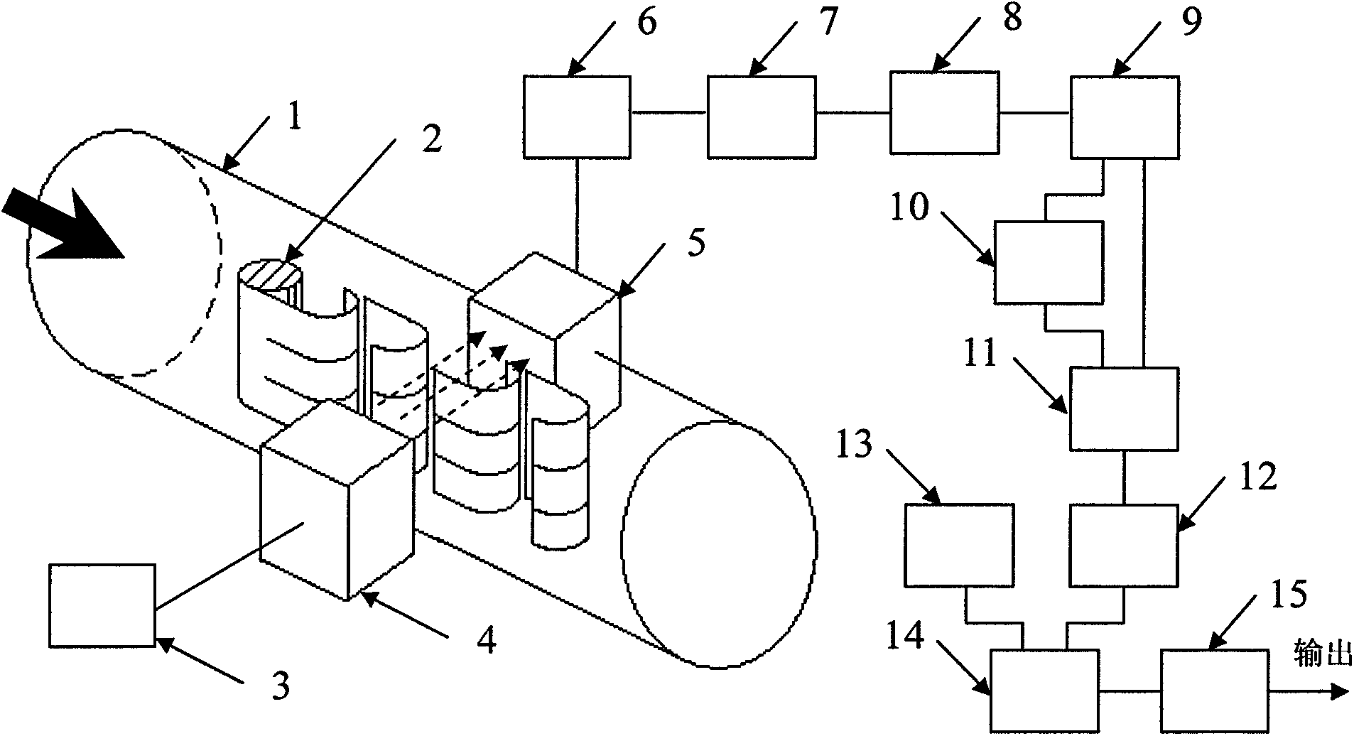
[0030] See figure 1 , An ultrasonic vortex flowmeter, consisting of a vent pipe 1, a vortex generator 2, an ultrasonic oscillator 3, an ultrasonic transmitting crystal 4, an ultrasonic receiving crystal 5, a first amplifier 6, a geophone 7, a second amplifier 8, Schmidt The flip-flop 9, the delay 10, the first multiplier 11, the first integrator 12, the oscillator 13, the second multiplier 14, the second integrator 15 and so on. The output of the ultrasonic oscillator 3 is connected to the input of the ultrasonic transmitting crystal 4, the output of the ultrasonic receiving crystal 5 is connected to the input of the first amplifier 6, the output of the first amplifier 6 is connected to the input of the detector 7, and the output of the detector 7 is connected. To the input of the second amplifier 8, the output of the second amplifier 8 is connected to the input of the Schmitt trigger 9, the output of the Schmitt trigger 9 is connected to the input of the delay 10, and at the sa...

Embodiment 2

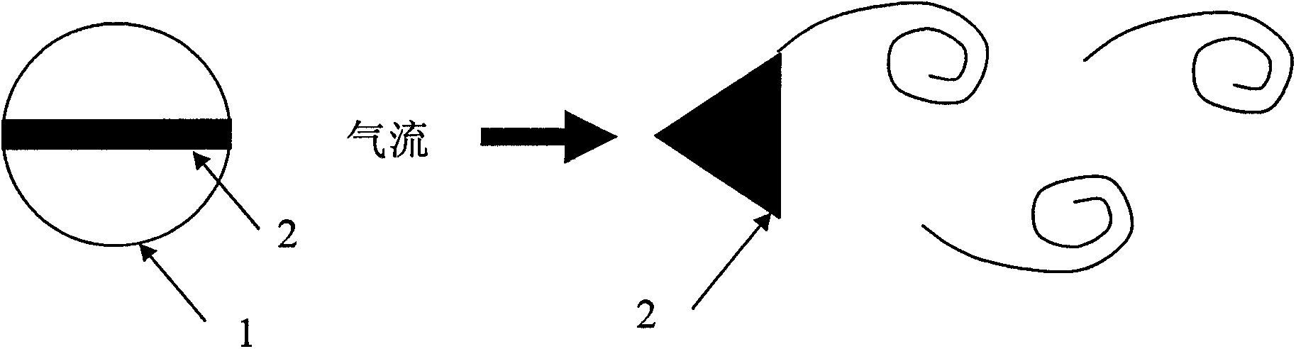
[0039] See figure 2 , The vortex generator 2 is a triangular column, which runs through the ventilation duct 1, and a vertex of the triangular column faces the direction of air flow. The ratio of the cross-sectional area of ​​the triangular cylinder facing the air flow direction to the cross-sectional area of ​​the air duct 1 is 1:50-1:2000.

Embodiment 3

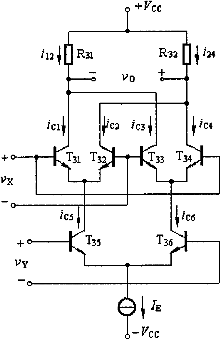
[0041] See image 3 , The first multiplier 11 and the second multiplier 14 are composed of a transistor T 31 , T 32 , T 33 , T 34 , T 35 , T 36 , Resistance R 31 , R 32 Double-balanced four-quadrant multiplier composed of other components, the input is v 1 And v 2 , The output is v o And there are:

[0042] v o =K m v x v y (3)

[0043] Where Is the multiplication coefficient, I E For T 35 And T 36 Emitter current, V T Is the cut-off voltage of the triode. In order not to saturate the output of the first multiplier 11 and the second multiplier 14 and cause the measurement range to be too small, the resistance R is adjusted 31 , Emitter current I E And choose the appropriate transistor cut-off voltage V T , So that the multiplication coefficient K m Between 0.01 and 10.


PUM


Abstract

The invention discloses an ultrasound vortex flowmeter, which consists of an air duct 1, a vortex generator 2, an ultrasonator 3, an ultrasonic transmitting crystal 4, an ultrasonic receiving crystal 5, a first amplifier 6, a detector 7, a second amplifier 8, a Schmitt trigger 9, a delayer 10, a first multiplying unit 11, a first integrator 12, an oscillator 13, a second multiplying unit 14 and a second integrator 15. The frequency corresponding to an output power spectrum peak value is the vortex shedding frequency f. The flowmeter has the following beneficial effects that (1) the vortex shedding frequency f is detected with a power spectrum method, which is favorable for improving the frequency numerical reading stability; (2) an electronic circuit is adopted to realize the power spectrum detection, which is favorable for improving the numerical reading instantaneity; and (3) the triangular cylinder vortex generator 2 is adopted, which is favorable for improving the ultrasound modulation function by the vortex and reducing pressure loss. The flowmeter has the characteristics of small pressure loss, low measurement sensitive limit and wide span range and can carry out bidirectional measurement.

Description

Technical field [0001] The present invention belongs to the field of instrumentation, and relates to a flow meter, specifically, to a Carmen vortex generated in the gas by a vortex generator to modulate the amplitude of the ultrasonic wave propagating in the gas, and to detect the frequency of the ultrasonic modulation signal Flow meter for measuring gas flow. Background technique [0002] The artificial respirator is a medical instrument for rescue and life support. The ventilation volume of the artificial ventilator determines the gas exchange of the alveoli, which requires real-time monitoring. In the 1970s and 1980s, the artificial respirator did not have a flow meter to measure the ventilation. This parameter is basically given by the doctor’s experience, which affects the ventilation quality and breathing safety of the respirator. Ventilation flow meters were commonly used in artificial ventilators in the late 1980s to monitor respiratory ventilation. [0003] The ventilat...

Claims


Application Information

Patent Timeline
Patent Type & Authority Applications(China)
IPC IPC(8): G01F1/66
Inventor 包家立
Owner HANGZHOU SHEZHANG TECH
Why Eureka
Try Eureka