Power conversion circuit and power conversion system

A technology for converting circuits and power, applied in the direction of converting AC power input into DC power output, irreversible AC power input into DC power output, output power conversion device, etc. Complicated problems, to achieve the effect of simplifying the control logic

Active Publication Date: 2013-12-25
HUAWEI DIGITAL POWER TECH CO LTD
View PDF5 Cites 39 Cited by
  • Summary
  • Abstract
  • Description
  • Claims
  • Application Information

AI Technical Summary

Problems solved by technology

However, the control logic of the inverter circuit in this scheme is complex and not easy to implement

Method used


Image

  • Power conversion circuit and power conversion system
  • Power conversion circuit and power conversion system
  • Power conversion circuit and power conversion system

Examples


Embodiment Construction

[0043]The following will clearly and completely describe the technical solutions in the embodiments of the present invention with reference to the accompanying drawings in the embodiments of the present invention. Obviously, the described embodiments are some of the embodiments of the present invention, but not all of them. Based on the embodiments of the present invention, all other embodiments obtained by persons of ordinary skill in the art without creative efforts fall within the protection scope of the present invention.

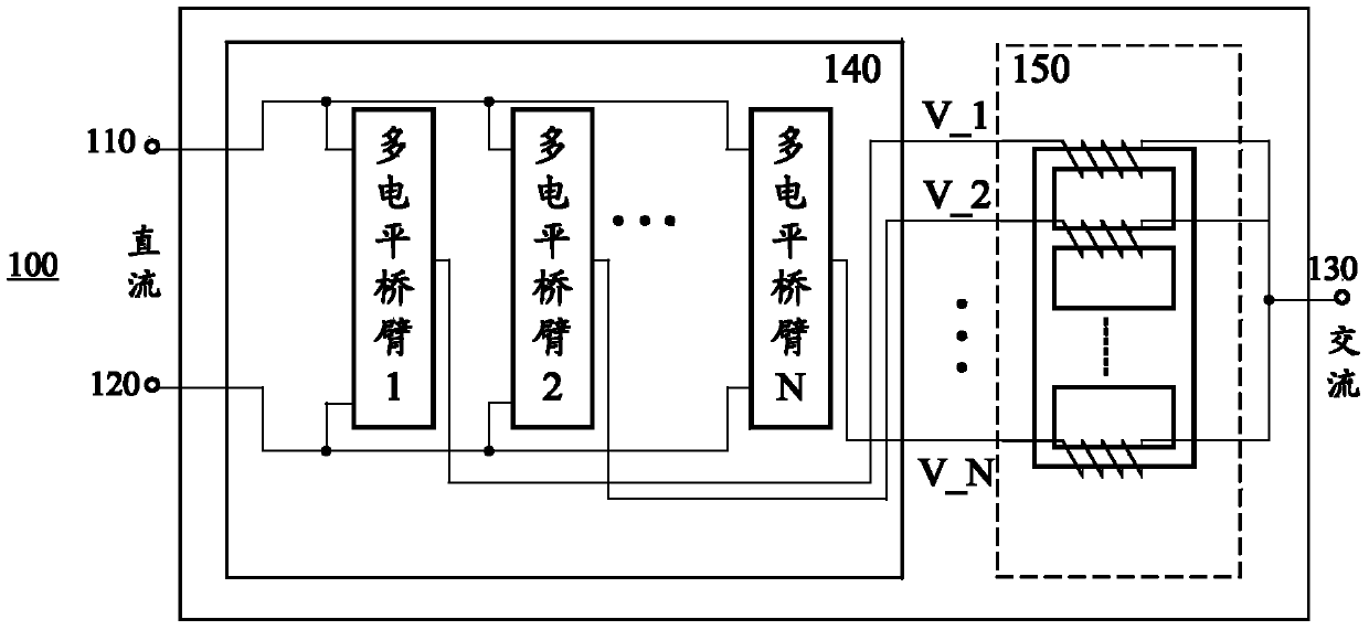
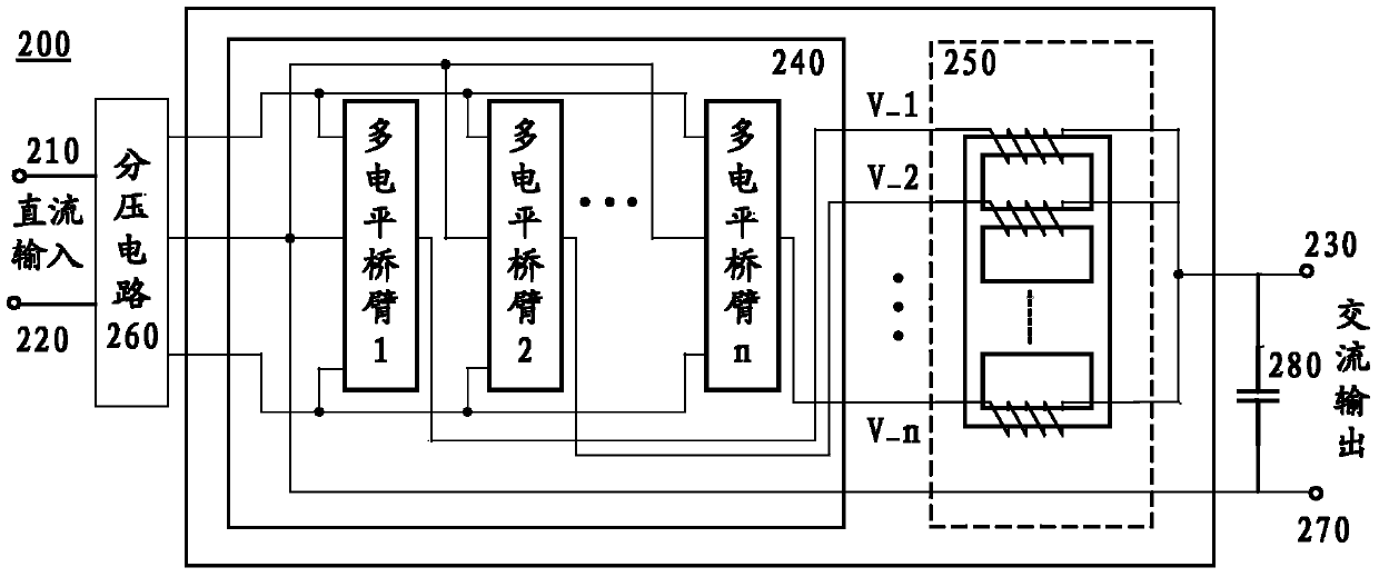
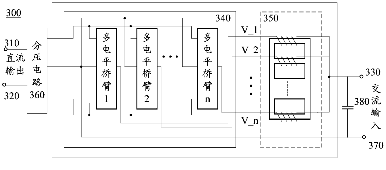
[0044] Interleaved parallel technology is an effective solution to improve the power capacity of the power converter. The staggered parallel scheme can not only increase the power level of the converter conveniently, but also reduce the input and output current ripple, improve the dynamic response of the converter, reduce the volume of the magnetic components in the circuit and realize the current conversion. Automatic current sharing of the device. Al...


PUM


Abstract

The embodiment of the invention provides a power converter. The power converter comprises a first terminal, a second terminal, a third terminal and N paths of multi-level bridge arms, wherein the first terminal and the second terminal are connected with a direct current, the third terminal is connected with an alternating current, the N paths of multi-level bridge arms are connected to the first terminal and the second terminal in parallel, the N paths of multi-level bridge arms work in a staggered and parallel manner, each multi-level bridge arm of the N paths of multi-level bridge arms comprises alternating current nodes, multiple time-varying levels are generated at the alternating current nodes, and the quantity of the multiple time-varying levels is greater than two. The power converter further comprises a coupling inductor, wherein the coupling inductor comprises N windings coupled by a common magnetic core, one end of each winding of the N windings is connected with the alternating current nodes of one multi-level bridge arm of the N paths of multi-level bridge arms respectively, and the other end of each winding of the N windings is connected to the third terminal. Due to the technical scheme of the invention, the control logical of the power converter is simplified.

Description

technical field [0001] Embodiments of the present invention relate to power conversion technology, and in particular, to a power conversion circuit and a power conversion system. Background technique [0002] In the existing high-voltage inverter technology, the high-voltage inverter based on the direct series connection of power electronic devices has high requirements for dynamic and static voltage equalization circuits, and the high-order harmonic content of the output voltage is high, so an output filter needs to be installed. The proposal of the multi-level inverter circuit has made breakthrough progress in solving the above problems. The general structure of the multi-level inverter is to synthesize a ladder wave in several stages to approximate the sinusoidal output voltage. Due to the increase in the number of output voltage levels of this inverter, the harmonic content of the output waveform is reduced, the voltage stress on the switch is reduced, and there is no n...

Claims


Application Information

Patent Timeline
Patent Type & Authority Applications(China)
IPC IPC(8): H02M7/483H02M7/487H02M7/12
CPCH02M1/12H02M7/487H02M7/493H02M7/23H02M1/14H02M7/483H02M1/0064H02M1/0043H02M7/4837
Inventor 胡炎申刘云峰石磊
Owner HUAWEI DIGITAL POWER TECH CO LTD
Why Eureka
Try Eureka