Unlock instant, AI-driven research and patent intelligence for your innovation.

Voltage-controlled oscillator

A technology of voltage-controlled oscillator and ring oscillator, applied in the direction of automatic power control, electrical components, etc., can solve the problem of low output signal frequency

Active Publication Date: 2013-12-25
BRIGATES MICROELECTRONICS KUNSHAN
View PDF6 Cites 7 Cited by
  • Summary
  • Abstract
  • Description
  • Claims
  • Application Information

AI Technical Summary

Problems solved by technology

[0014] The present invention solves the problem that the frequency of the output signal of the existing voltage-controlled oscillator is low when it works under low power supply voltage

Method used


Image

  • Voltage-controlled oscillator
  • Voltage-controlled oscillator
  • Voltage-controlled oscillator

Examples


Embodiment 1

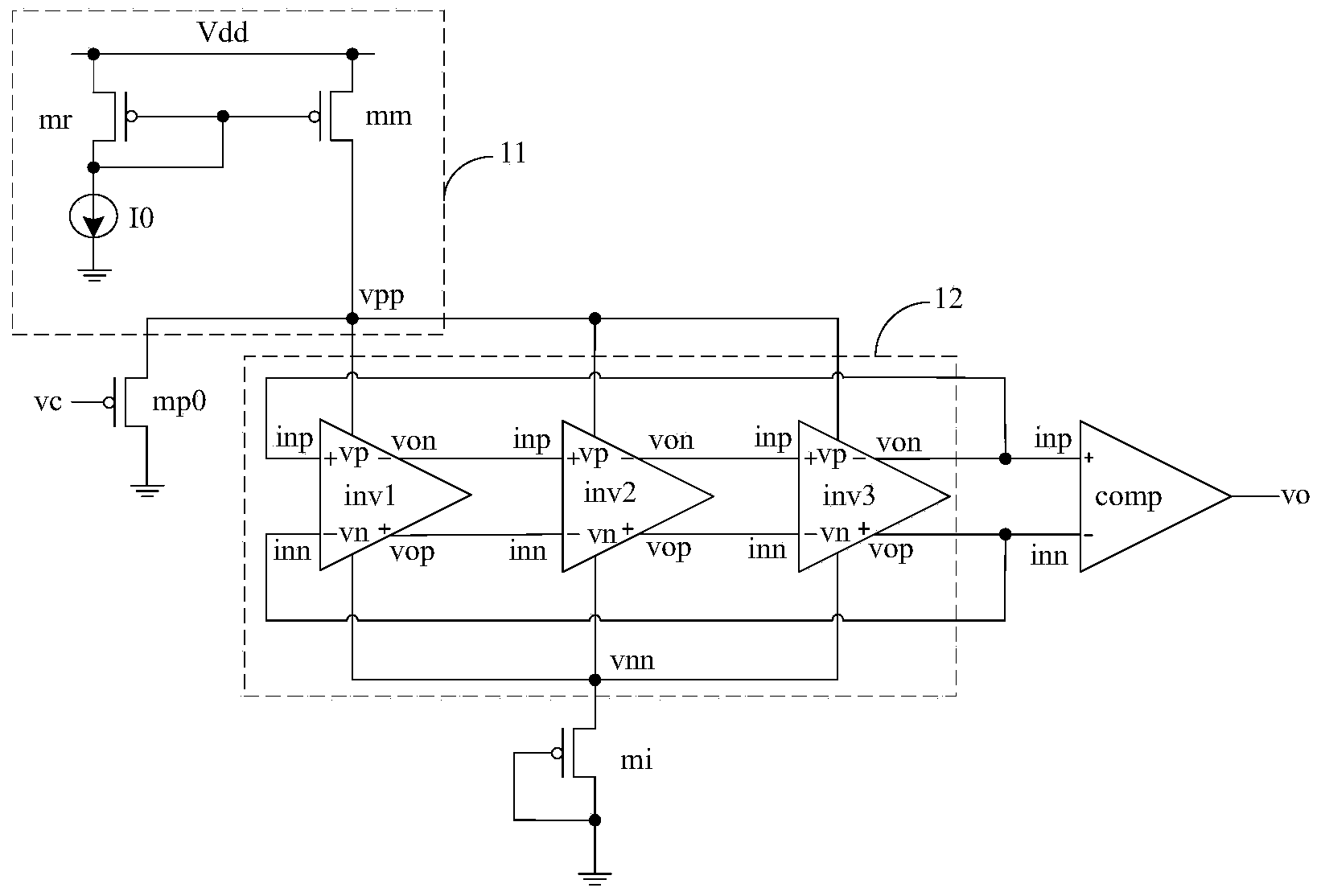
[0056] figure 2 is a circuit diagram of the voltage-controlled oscillator according to Embodiment 1 of the present invention. refer to figure 2 , the voltage-controlled oscillator includes a current mirror circuit 21, a fully differential ring oscillator 22, a voltage regulation unit 23, an input PMOS transistor MP0, and a differential-to-single-ended circuit COMP.

[0057] Specifically, the current mirror circuit 21 includes a reference transistor Mr, a mirror transistor Mm and a reference current source I0.

[0058] The first electrode of the reference transistor Mr is connected to the first electrode of the mirror transistor Mm and is suitable for inputting the power supply voltage Vdd of the voltage-controlled oscillator, and the second electrode of the reference transistor Mr is connected to the gate and connected to The gate of the mirror transistor Mm and one terminal of the reference current source I0 ; the other terminal of the reference current source I0 is groun...

Embodiment 2

[0085] image 3 is a circuit diagram of a voltage-controlled oscillator according to Embodiment 2 of the present invention. refer to image 3 , the voltage-controlled oscillator includes a current mirror circuit 31, a fully differential ring oscillator 32, a voltage adjustment unit 33, an input PMOS transistor MP0, and a differential-to-single-ended circuit COMP. Embodiment 2 Compared with Embodiment 1, the voltage-controlled oscillator further includes a level shift circuit 34, and the level shift circuit 34 is adapted to reduce the control voltage vc and then input it into the input PMOS transistor MP0 the grid.

[0086] For the current mirror circuit 31 , the fully differential ring oscillator 32 , the voltage adjustment unit 33 , the input PMOS transistor MP0 and the differential-to-single-ended circuit COMP, reference may be made to the description in Embodiment 1, and details are not repeated here.

[0087] The level shift circuit 34 includes a first source follower a...

Embodiment 3

[0101] Figure 4 is a circuit diagram of a voltage-controlled oscillator according to Embodiment 3 of the present invention. refer to Figure 4 , the voltage-controlled oscillator includes a current mirror circuit 41, a fully differential ring oscillator 42, a voltage adjustment unit 43, a level down shift circuit 44, an input PMOS transistor MP0, and a differential-to-single-ended circuit COMP. Compared with Embodiment 2, Embodiment 3 differs in that: the first source follower further includes a resistor R, and the source of the second NMOS transistor MN2 is connected to the third NMOS transistor MN3 through the resistor R. drain and the gate of the input PMOS transistor MP0.

[0102] Specifically, one end of the resistor R is connected to the source of the second NMOS transistor MN2, and the other end of the resistor R is connected to the drain of the third NMOS transistor MN3 and the gate of the input PMOS transistor MP0.

[0103] The current mirror circuit 41, the fully...


PUM


Abstract

A voltage-controlled oscillator comprises an input PMOS tube, a current mirror circuit, a fully differential ring oscillator and a differential to single-ended circuit, wherein the grid electrode of the input PMOS pipe is suitable for inputting control voltage of the voltage-controlled oscillator, the output end of the current mirror circuit is connected with the source electrode of the input PMOS tube and the positive power supply end of the fully differential ring oscillator, the output end of the fully differential ring oscillator is connected with the input end of the differential to single-ended circuit, and the voltage-controlled oscillator further comprises a voltage regulating unit for controlling voltage of the negative power supply end of the fully differential ring oscillator to be reduced along with rising of control voltage. The voltage-controlled oscillator can enlarge the regulating range of the control voltage and output high-frequency signals under low supply voltage.

Description

technical field [0001] The invention relates to the technical field of integrated circuits, in particular to a voltage-controlled oscillator. Background technique [0002] A voltage-controlled oscillator (VCO, voltage-controlled oscillator) is one of the main components of a phase-locked loop (PLL, phase locked loop). Oscillation frequency, the periodic signal that makes the output frequency of the oscillator change linearly with the change of the control voltage. [0003] figure 1 It is a circuit diagram of an existing voltage-controlled oscillator. refer to figure 1 , the voltage-controlled oscillator includes: an input PMOS transistor mp0, a current mirror circuit 11, a fully differential ring oscillator 12, a differential-to-single-ended circuit comp, and a tail current source MOS transistor mi. [0004] Specifically, the gate of the input PMOS transistor mp0 is suitable for inputting a control voltage vc, and converting the control voltage vc into a control current....

Claims


Application Information

Patent Timeline
Patent Type & Authority Applications(China)
IPC IPC(8): H03L7/099
Inventor 黄从朝
Owner BRIGATES MICROELECTRONICS KUNSHAN