Ramp generator circuit, and image sensor and image capture device comprising same

A ramp signal and generating circuit technology, applied in signal transmission system, electrical signal transmission system, image communication, etc., can solve problems such as clock waveform passivation, duty cycle degradation, differential nonlinear) characteristic degradation, etc.

Inactive Publication Date: 2013-12-25
PANASONIC CORP
View PDF4 Cites 3 Cited by
  • Summary
  • Abstract
  • Description
  • Claims
  • Application Information

AI Technical Summary

Problems solved by technology

In addition, when the frequency of the clock is increased, the load due to wiring resistance and/or wiring capacitance will cause clock wavef...

Method used


Image

  • Ramp generator circuit, and image sensor and image capture device comprising same
  • Ramp generator circuit, and image sensor and image capture device comprising same
  • Ramp generator circuit, and image sensor and image capture device comprising same

Examples


no. 1 approach >

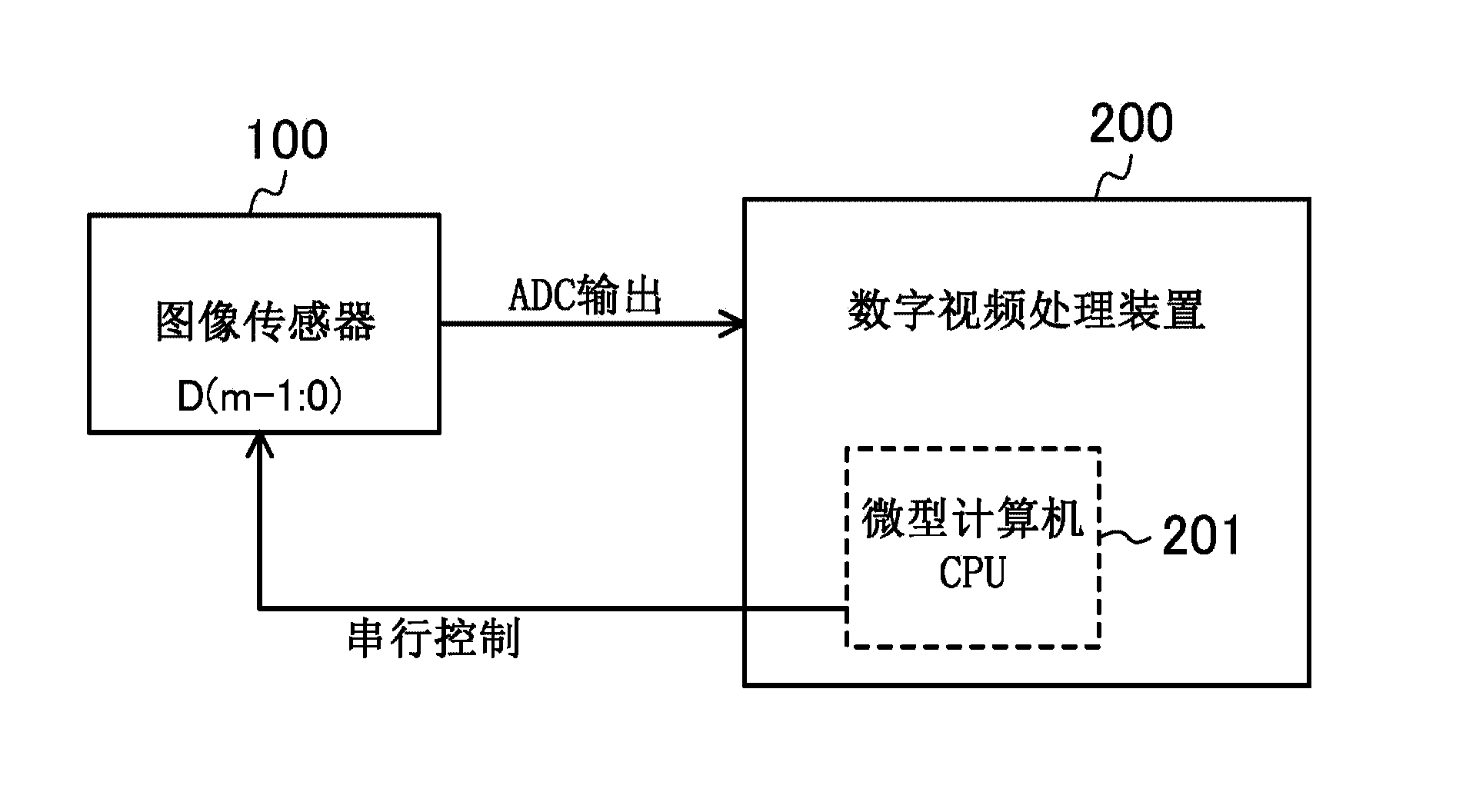
[0076] figure 1 It is a block diagram schematically showing the imaging device according to the first embodiment. exist figure 1 Among them, the camera device includes an image sensor 100 and a digital video processing device 200 .

[0077] The digital video processing device 200 has a microcomputer CPU201, utilizes the serial control signal D(m-1:0) (m is a natural number greater than or equal to 2) from the microcomputer CPU201 to control the image sensor 100, and according to the input from the image sensor 100 The digital signal (ADC output signal) for video signal processing.

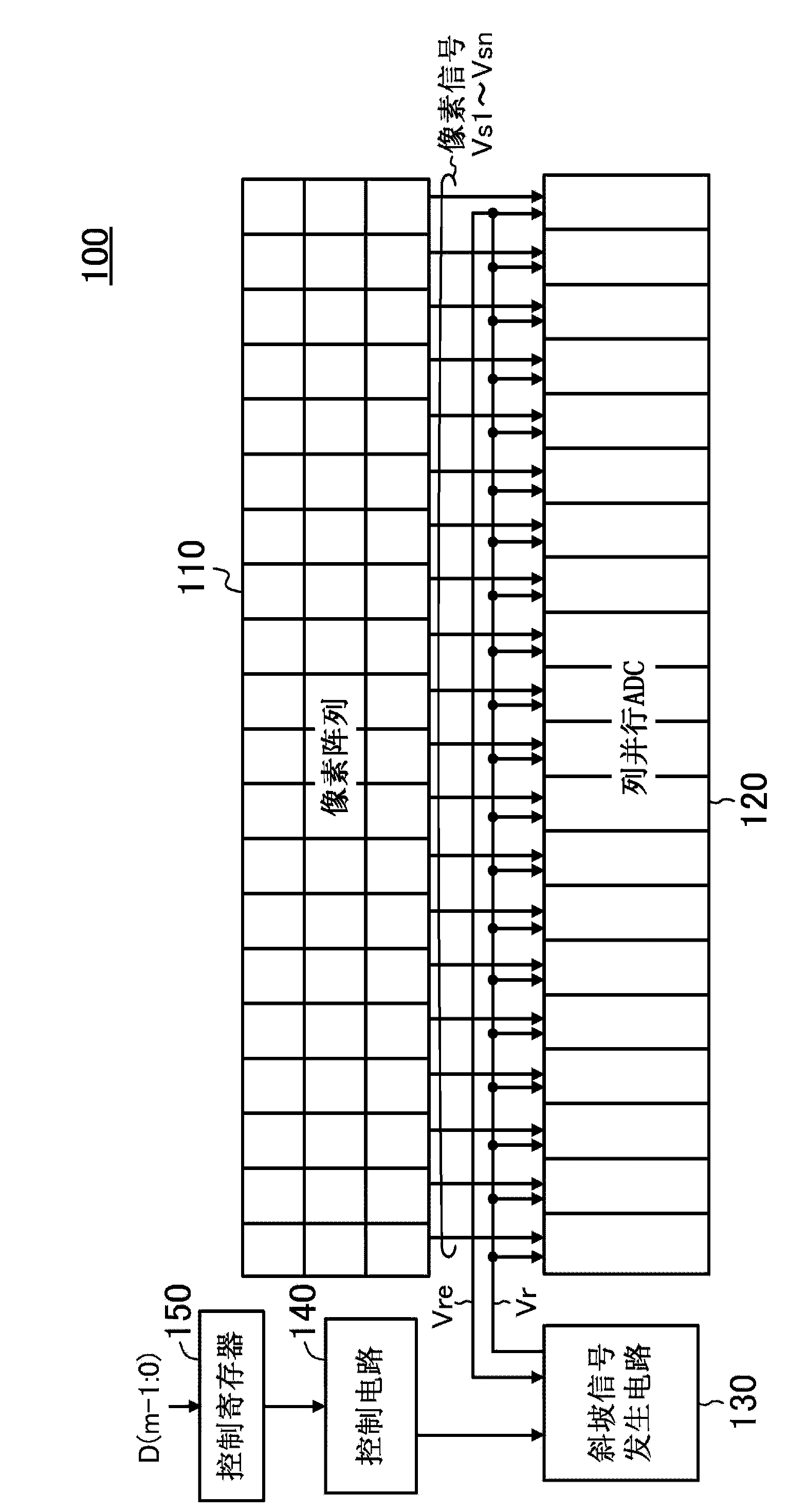
[0078] figure 2 It is a block diagram schematically showing the image sensor 100 according to the first embodiment. exist figure 2 Among them, the image sensor 100 includes: a pixel array 110 , a column-parallel ADC (single-slope ADC) 120 , a ramp signal generating circuit 130 , a control circuit 140 and a control register 150 .

[0079] The pixel array 110 is composed of unit pixels comp...

no. 2 approach >

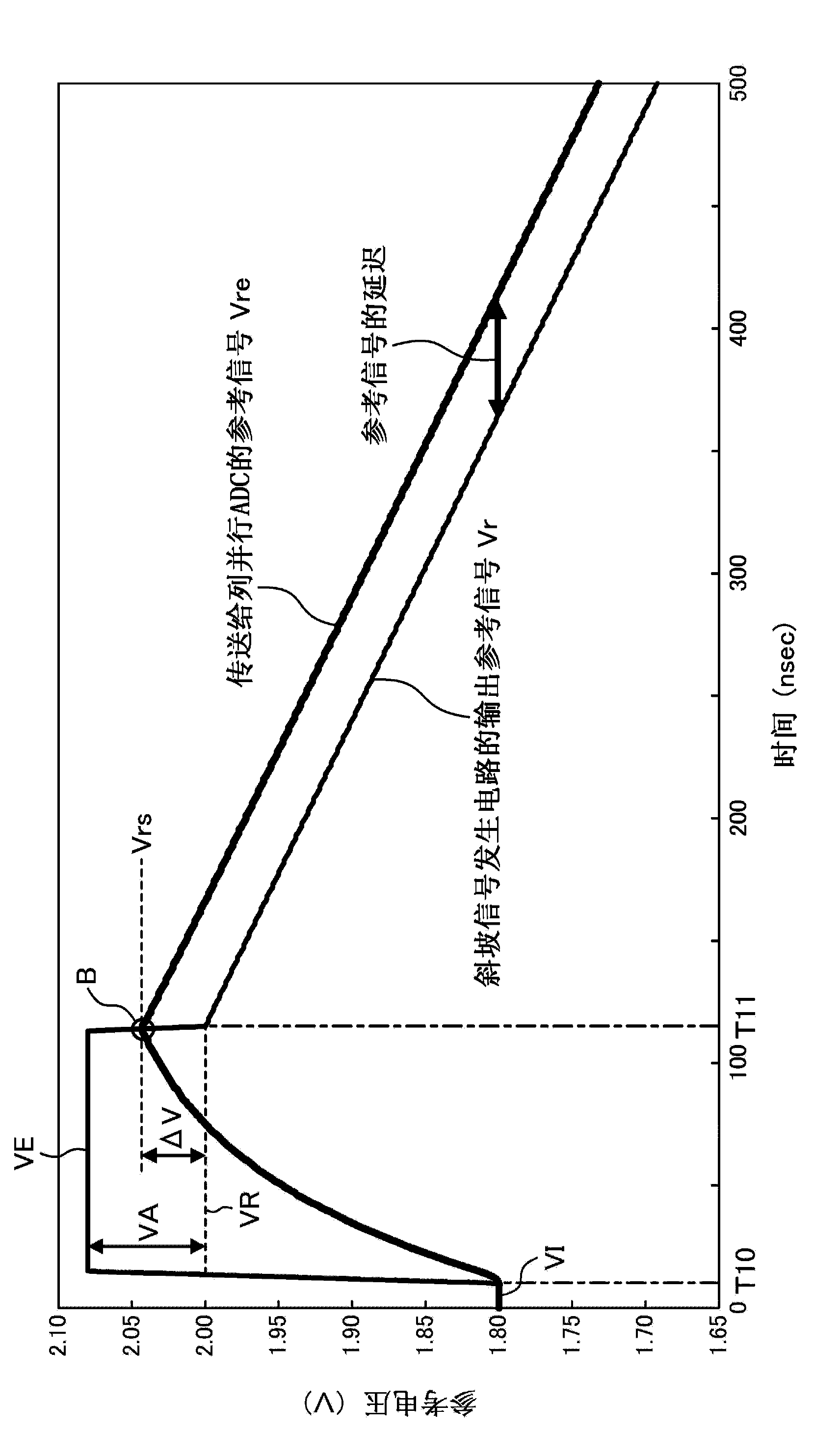
[0124] Figure 10 It is a diagram showing a configuration example of a ramp signal generating circuit and a connection example of peripheral circuits according to the second embodiment. exist Figure 10 Neutral and Figure 5 The same component labeling and Figure 5 The same symbols are used, and their detailed descriptions are omitted here.

[0125] exist Figure 10 The ramp signal generation circuit 130A with Figure 5 The difference is that a voltage comparison unit 137 is included instead of the time difference comparison unit 132 , and a voltage measurement unit 135 and a reference voltage measurement unit 136 are further included. Here, the calibration of the initializing voltage VE of the control comparator is repeatedly performed during a period in which the image output of the imaging device is invalid, etc. Hereinafter, the calibration performed for the first time will be referred to as the first cycle calibration, and the calibration performed for the second ti...


PUM


Abstract

A ramp generator circuit (130) comprises a reference voltage generator unit (134), which, prior to a comparison operation of an analog-digital conversion circuit (120), converts a voltage of a reference signal (Vr) to a comparison apparatus setting voltage (VR) which corrects a voltage disparity between the reference signal (Vr) and an analog input signal (Vs1-Vsn), and outputs a ramp signal as a base point of the comparison apparatus setting voltage (VR) together with the commencement of the comparison operation. The ramp generator circuit (130) further comprises a function which adds a prescribed enhanced voltage (VA) to the comparison apparatus setting voltage (VR) prior to the comparison operation.

Description

technical field [0001] The present invention relates to an image sensor and an imaging device, in particular to a single slope (single slope) (also called integral or counting) analog-to-digital conversion circuit (hereinafter referred to as In this paper, it is referred to as ADC (Analog-to-Digital Converter)) to output the ramp signal generating circuit of the reference signal. Background technique [0002] So far, image sensors employing a column parallel AD conversion method (column parallel AD conversion) in which ADCs are respectively provided for each column in a pixel array of the image sensor are being developed and used, and During the horizontal scanning period, an AD (Analog-to-Digital) conversion process is performed on the pixel output signals of one row of the pixel array. In this column-parallel AD conversion method, since the area of ​​each column determined by the pixel pitch is constrained, a single-slope ADC with a small circuit scale is generally used (...

Claims


Application Information

Patent Timeline
IPC IPC(8): H04N5/378H03M1/56
CPCH03M1/0612H03M1/123H03M1/742H03K4/06H03M1/56H04N25/677H04N25/75
Inventor 樋口真浩西村佳寿子山冈优介阿部豊藤中洋
Owner PANASONIC CORP
Why Eureka
Try Eureka