Wire harness support forming die

A technology for forming molds and wire harness brackets, which is applied in the field of mechanical processing, can solve the problems that the dimensional accuracy cannot meet the technical requirements, the parts cannot reach the matching state, and the consistency of the parts is poor, so as to achieve good consistency, easy operation and low manufacturing cost.

Inactive Publication Date: 2014-01-01
HENGYANG FENGSHUN AXLE CO LTD
View PDF0 Cites 4 Cited by
  • Summary
  • Abstract
  • Description
  • Claims
  • Application Information

AI Technical Summary

Problems solved by technology

[0002] The wire harness bracket is an important part of the car. It is used in the reducer assembly. Its main function is to increase the test safety protection performance, so it requires high matching accuracy. At present, the wire harness bracket is made by hand. The wire-cut sheet is clamped in a vise and manually formed with a hammer. Only one product can be formed at a time. Therefore, with this production method, the consistency of parts processing is poor, and the dimensional accuracy cannot meet the technical requirements. The appearance quality is poor, the production efficiency is low, the production cost is high, and the matching parts cannot be matched well

Method used


Image

  • Wire harness support forming die
  • Wire harness support forming die
  • Wire harness support forming die

Examples


Embodiment Construction

[0031] As shown in the accompanying drawings: a wire harness bracket molding die, which includes an upper die assembly and a lower die assembly.

[0032] The upper mold assembly includes: a mold handle 1, an upper mold base 2, a backing plate 3, a screw 4, a punch 5, a cylindrical pin 12, a positioning pin 18, a hexagon socket bolt 19, and a guide sleeve 17.

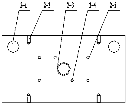
[0033] The upper mold base 2 includes: guide sleeve installation hole 2-1, upper mold hoisting hole 2-2, mold handle installation hole 2-3, backing plate positioning hole 2-4, backing plate installation hole 2-5, guide Sleeve mounting holes 2-1 are located on both sides of the front of the upper die base, upper die lifting holes 2-2 are located on the four corners of the upper die base side, mold handle installation holes 2-3 are located in the center of the upper die base, pads Plate mounting holes 2-5 are located around the mold handle mounting holes, and backing plate positioning holes 2-4 are located near the backing...


PUM


Abstract

The invention discloses a wire harness support forming die which comprises an upper die assembly and a lower die assembly. The upper die assembly comprises a die shank, an upper die holder, a base plate, a screw, a male die, a cylindrical pin, a positioning pin, an inner hexagon bolt and two guide sleeves; the lower die assembly comprises an ejector plate, an ejector pin, a lower die holder, an insert, inner hexagon screws, two female dies, a positioning plate, positioning rings, a bolt and two guide columns; the die shank is positioned in the middle of the upper die holder, the base plate is positioned in the middle of the lower side of the upper die holder, the male die is positioned in the middle of the lower side of the base plate, the two guide sleeves are respectively positioned on the left and the right of the front of the upper die holder, the insert is positioned in an I concave table of the lower die holder, the two female dies are respectively positioned on two sides of the middle of the insert, the ejector plate is positioned in the middle of the insert, one end of the ejector pin is positioned on the lower side of the ejector plate, the other end of the ejector pin is penetratingly arranged in an ejector pin hole of the insert, the positioning plate is positioned above the female dies, and the two guide columns are respectively positioned on the left and the right of the front of the lower die holder. The wire harness support forming die has the advantages that four products can be formed by the wire harness support forming die at one step, and the wire harness support forming die can be operated easily and conveniently and is high in production efficiency.

Description

technical field [0001] The invention relates to a cold stamping die in the field of mechanical processing, in particular to a wire harness bracket forming die. Background technique [0002] The wire harness bracket is an important part of the car. It is used in the reducer assembly. Its main function is to increase the test safety protection performance, so it requires high matching accuracy. At present, the wire harness bracket is made by hand. The wire-cut sheet is clamped in a vise and manually formed with a hammer. Only one product can be formed at a time. Therefore, with this production method, the consistency of parts processing is poor, and the dimensional accuracy cannot meet the technical requirements. The appearance quality is poor, the production efficiency is low, the production cost is high, and the matching parts cannot be matched well. Contents of the invention [0003] The object of the present invention is to overcome the above-mentioned shortcomings of t...

Claims


Application Information

Patent Timeline
IPC IPC(8): B21D37/10
Inventor 尢华胜刘登发
Owner HENGYANG FENGSHUN AXLE CO LTD
Why Eureka
Try Eureka