A multi-functional high-efficiency lubricating oil purification process device

A technology for purifying device and lubricating oil, applied in the direction of lubricating composition, etc., can solve problems such as premature aging of oil, equipment failure, inability to clean, etc., and achieve the effect of prolonging service life, improving efficiency and improving oil quality

Active Publication Date: 2019-05-24
BAOTOU RUINUO JINGTU NEO MATERIAL
View PDF7 Cites 1 Cited by
  • Summary
  • Abstract
  • Description
  • Claims
  • Application Information

AI Technical Summary

Problems solved by technology

[0005] In the above technical methods and equipment, the degree of treatment of dirty oil is limited, and it is difficult to achieve the ideal purification target of oil. Due to historical factors and factors of one-time input cost, the filtering method is the dominant method so far, which also leads to pollution. There are many problems in the deep purification and high recycling of oil, the specific comparison is as follows:
[0006] For filter equipment, due to the very fine particles mixed in the oil, the high viscosity of the oil and the presence of carbon black and colloids, the blocking effect of the filter cannot reach a higher level, otherwise the oil cannot pass through. , very limited even with pressurization, and cannot be cleaned
The general filtration method can not remove the moisture in the oil, so the degree of purification is very limited, and it is very easy to block, the filter element is replaced frequently, and the management is not in place, which can easily cause equipment failure. Since the filter element is difficult to regenerate, it can only be treated as waste. Although the filter paper It is relatively cheap, but it cannot be cleaned, the usage is large, the waste is difficult to dispose of or it is easy to cause secondary pollution. The same problem exists in the metal filter element, which increases the long-term operation cost of the production facility.
[0007] The main principle of the coalescing equipment is not much different from that of the filter element, except that smaller microporous hydrophobic materials are used to block the passage of the emulsion, but it does not work at all for natural water and bound water, and the dehydration efficiency is low.
[0008] The main function of evaporative equipment is to remove gas and moisture. Since a large amount of energy is used to heat the oil, and then the boiling point is reduced by vacuum to increase the evaporation rate, this method is very costly to deal with dirty oil, especially it is easy to make the oil prematurely. Aging relatively offsets the overall value of regeneration treatment, but also increases more hidden dangers and costs
[0009] The centrifugal purification method is a new technology that has only emerged in recent years. It separates the particles and water in the oil through high-speed rotating centrifugation, and can also discharge part of the gas, so it can achieve the effect of three-phase separation, and the speed is also faster. , is also a single device with relatively complete functions, but due to the characteristics of the mechanism itself, it can only separate particulate matter and water that are heavier than oil, but has no effect on light matter (carbon black) and colloids (oxides). The treatment of oil is difficult to achieve a better level, and there is little improvement in the color produced by colloids and carbon black

Method used


Image

  • A multi-functional high-efficiency lubricating oil purification process device

Examples


Embodiment 1

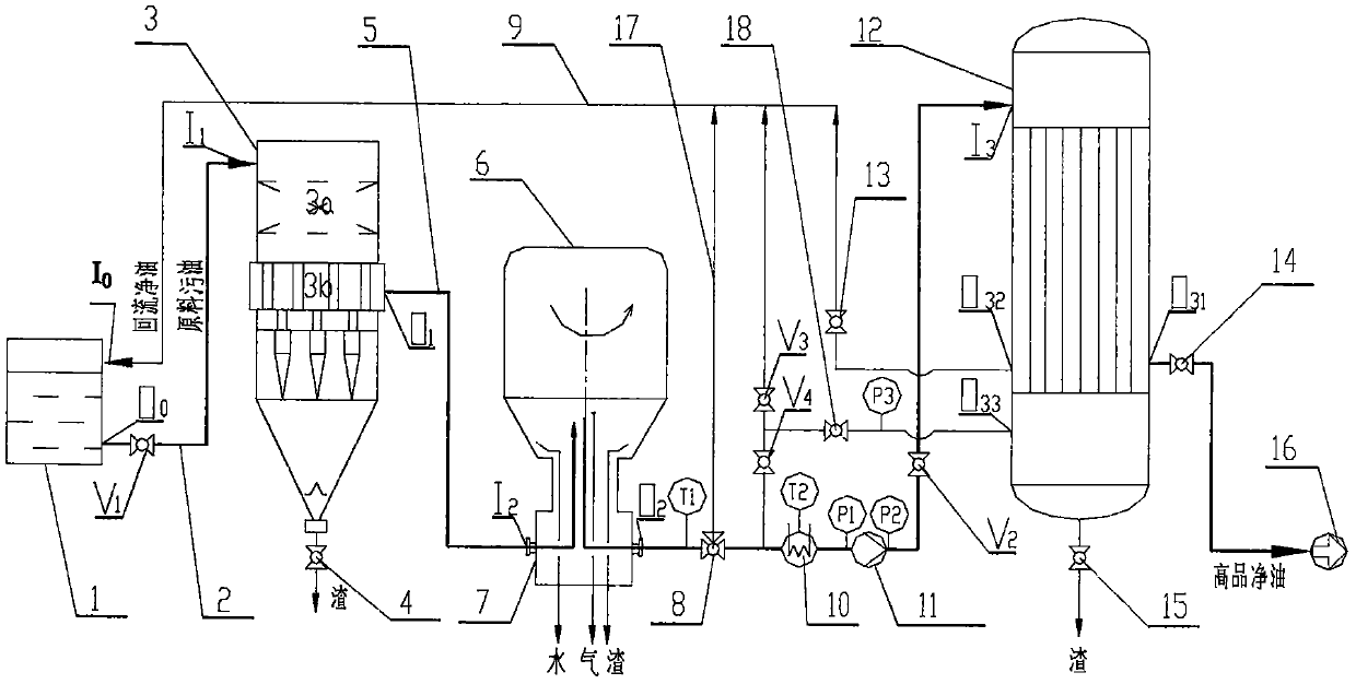
[0062] 1.2m from the power plant 3 The polluted 36# turbine oil is put into the oil storage tank 1, and under the action of the negative pressure pump in the centrifuge 6, the 3 The flow rate of / h flows into the magnetic cyclone 3 through the suction pipe 2 for initial slag removal, and then enters the centrifuge 6 through the first connecting pipe 5, and separates at a speed of 8000-12000r / min. The separated oil From outlet O of centrifuge 6 2 Return to the oil storage tank 1 through the first circuit and circulate and purify again. After running like this for 30 minutes, stop the machine and take samples for detection. Filter out 12.5 grams of coarse slag from the sewage valve 4 of the slag discharge port of the magnetic cyclone 3. 85.2 grams of water and slag were taken out from 7 places. After testing, the pollution degree of the oil decreased from 12 to 8, the water content decreased from 0.6% to 0.005%, the dissolved gas content decreased from 2% to 0.15%, and the chr...

Embodiment 2

[0064] 1.5m from the rolling mill of the iron and steel plant 3 The contaminated 525 rolling mill oil is put into the oil storage tank 1, and under the action of the negative pressure pump in the centrifuge 6, the 3 The flow rate of / h flows into the magnetic cyclone 3 through the suction pipe 2 for initial slag removal, and then enters the centrifuge 6 through the first connecting pipe 5, and separates at a speed of 8000-12000r / min. The separated oil Switch to the heater 10 through the three-way valve 8, after being heated by the heater to 30-80°C, pressurized by the circulation pump 11, and go to the fine filter 12, and the finely filtered oil flows from the liquid outlet O of the fine filter 32 Return to the oil storage tank 1 through the second circuit for circulation treatment, after running for 60 minutes like this, stop and take a sample for detection, filter out 15.2 grams of coarse slag from the blowdown valve 4 of the slag discharge port of the magnetic cyclone 3, an...

Embodiment 3

[0066] Take Steel Plant BP46#1.2m 3 The contaminated 525 hydraulic oil is put into the oil storage tank 1, and under the action of the negative pressure pump in the centrifuge 6, it is 3 The flow rate of / h flows into the magnetic cyclone 3 through the suction pipe 2 for initial slag removal, and then enters the centrifuge 6 through the first connecting pipe 5, and separates at a speed of 8000-12000r / min. The separated oil Switch to the heater 10 through the three-way valve 8. After being heated to 30-80°C by the heater, the circulation pump 11 pressurizes and goes to the fine filter 12. Liquid port O 32 Return to the oil storage tank 1 through the second loop for circulation treatment, and the other path passes through the liquid outlet O of the fine filter 12 33 Regulate the reflux pressure P3 through the reflux valve 18 to control the total reflux flow, and then return to the reflux pipe 9 and the heater 10 through the check valves V3 and V4. After running for 60 minutes,...


PUM

PropertyMeasurementUnit
pore sizeaaaaaaaaaa

Abstract

The invention relates to a purifying device and method for polluted lubricating oil (i.e., dirty oil). The device comprises a magnetic rotator, a centrifuge and a fine filter which are connected sequentially, wherein a liquid outlet of the magnetic rotator is connected with a liquid inlet of the centrifuge through a first adapting pipe, and a liquid outlet of the centrifuge is connected with a liquid inlet of the fine filter through a pipeline. According to the device and the method disclosed by the invention, methods such as rotating-magnetic coagulation, centrifugal separation and membrane type refined filtration are organically combined, so that deep purification of the polluted lubricating oil is achieved; and the restraint, i.e., singleness of the existing equipment is overcome, various impurities such as enginery, water, air and oxidative colloids generated during the use of various kinds of lubricating oil can be effectively removed, the liquid quality of the lubricating oil is remarkably improved, running equipment is reliably guaranteed, the service life of liquid oil is substantially prolonged, the consumption of the lubricating oil is lowered, the cost of the lubricating oil is reduced, the environmental pollution caused by waste liquid oil is reduced, and great direct or indirect economic benefit is produced.

Description

technical field [0001] The invention relates to the technical field of lubricating oil purification, in particular to a multi-functional, combined lubricating oil efficient purification complete set of process system equipment. Background technique [0002] With the development of science and technology, the level of mechanization and automation of the industry is constantly improving, and the use of lubricating oil, which is indispensable for mechanical operation, is increasing, and it is used in all aspects of equipment such as lubrication, cooling and hydraulic transmission. Quality and maintenance management directly affects the normal operation of the entire production system, and is related to the safety, quality and efficiency of the enterprise. Therefore, people vividly call lubricating oil the "blood" of the machinery industry. Since the lubricating oil is continuously cyclically heated and aged during use, coupled with factors such as mechanical friction, local da...

Claims


Application Information

Patent Timeline
Patent Type & Authority Patents(China)
IPC IPC(8): C10M175/00
CPCC10M175/0025C10M175/0058C10M175/0066C10M175/0083
Inventor 马嘉东吕保义马克印李佳蓉
Owner BAOTOU RUINUO JINGTU NEO MATERIAL
Why Eureka
Try Eureka