Copper alloy die machining device and machining process

A mold processing and copper alloy technology, applied in the field of mechanical equipment, can solve the problems of low production efficiency, large consumption of profiles, high production cost, etc., and achieve the effects of high production efficiency, low production cost and stable quality

Inactive Publication Date: 2014-01-22
FUZHOU YINSHENGWANG SANITARY WARE
View PDF5 Cites 1 Cited by
  • Summary
  • Abstract
  • Description
  • Claims
  • Application Information

AI Technical Summary

Problems solved by technology

[0002] The traditional manufacturing process of faucets made of copper, copper alloy faucet blanks are the main parts (copper alloy workpiece 3), raw materials are profiles, and lathes and milling machines are mainly used for processing and manufacturing to meet product design requirements. The production efficiency is low. Due to The cost of profiles is high, and the consumption of profiles by lathes and milling machines is relatively high, so the production cost is relatively high; after technical transformation, special casting technology is used to reduce the consumption of raw materials. In order to improve production efficiency, a copper alloy mold with less cutting is designed The processing device is to process the copper alloy faucet blank as the main part (copper alloy workpiece 3), optimize the manufacturing process, ensure product quality, and reduce manufacturing costs.

Method used


Image

  • Copper alloy die machining device and machining process
  • Copper alloy die machining device and machining process
  • Copper alloy die machining device and machining process

Examples


Embodiment 1

[0027] Embodiment 1: Processing YSW lead-free DR copper alloy faucet square body casting as an example:

[0028] YSW lead-free DR copper alloy faucet square body casting,

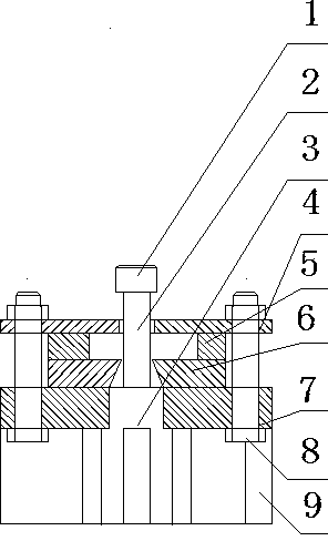
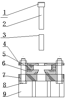
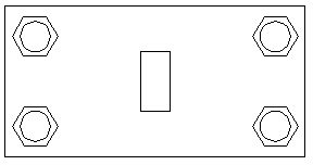
[0029] The mold installation adopts the coincidence of the pressure center and the center line of the hydraulic power mold shank to fix the lower mold base, which effectively eliminates the error caused by the bending moment movement of the blank during the cutting process. The structure of the mold processing device is as follows: figure 1 , 2 , 3, 4", this copper alloy mold processing device is divided into the upper part and the lower part, the upper part includes: hydraulic power mold handle 1, pressurized movable copper punch 2; the lower part includes: The upper fixed guide plate 4 , the chip discharge pad 5 , the cutting edge die 6 , the lower fixed cutting edge cushion 7 , the fixing bolts and nuts 8 , and the workpiece discharge cavity support 9 .

[0030] The upper fixed guide plate 4, the chip...


PUM


Abstract

The invention discloses a copper alloy die machining device and machining process. The copper alloy die machining device comprises an oil pressure power die handle (1), a cutting edge female die (6), a lower fixing cutting edge pedestal (7) and a workpiece discharging cavity support (9). The bottom end of the oil pressure power die handle (1) is connected with a pressurization movable copper male die (2). The cutting edge female die (6) is clamped between an upper fixing guide plate (4) and the lower fixing cutting edge pedestal (7). An upper through hole is formed in the center of the upper fixing guide plate (4). A cutting formed edge is formed in the center of the cutting edge female die (6). A lower through hole is formed in the center of the lower fixing cutting edge pedestal (7). The size of the upper through hole, the size of the lower through hole and the size of a cutting formed edge cavity are larger than the size of a die body of the pressurization movable copper male die (2). The pressurization movable copper male die (2) is guided into and can vertically move in the upper through hole, the lower through hole and the cutting formed edge. The lower fixing cutting edge pedestal (7) is installed on the workpiece discharging cavity support (9). A modern numerical control milling machine is replaced by the copper alloy die machining device to conduct machining, production efficiency is improved by multiple times, production, manufacturing and machining cost is reduced, and the quality of products is stable.

Description

technical field [0001] The invention belongs to the field of mechanical equipment, and relates to a copper alloy mold processing device, in particular to a faucet mold processing device made of copper. Background technique [0002] The traditional manufacturing process of faucets made of copper, the copper alloy faucet blank is the main part (copper alloy workpiece 3), the raw material is made of profiles, and the processing and manufacturing mainly use lathes and milling machines to meet the product design requirements, and its production efficiency is low. The cost of profiles is high, and the consumption of profiles by lathes and milling machines is relatively high, so the production cost is relatively high; after technical transformation, special casting technology is used to reduce the consumption of raw materials. In order to improve production efficiency, a copper alloy mold with less cutting is designed The processing device is to process the copper alloy faucet blan...

Claims


Application Information

Patent Timeline
Patent Type & Authority Applications(China)
IPC IPC(8): B21D28/02B21D28/14
Inventor 王茂学范慧玲胡焰林高权根卢金平黄美红
Owner FUZHOU YINSHENGWANG SANITARY WARE
Why Eureka
Try Eureka