Line control brake system pedal force simulation and braking force control system of electric car

A technology of electric vehicles and brake-by-wire, which is applied in the direction of electric braking systems, electric vehicles, hydraulic brake transmissions, etc., and can solve the problems of low braking energy recovery rate, poor braking feeling of the driver, hydraulic braking force and electric motor Braking force coordination and other issues to achieve the effect of good braking stability, uniform change, and reduced pedal stroke

Inactive Publication Date: 2014-01-01
BEIHANG UNIV
View PDF6 Cites 14 Cited by
  • Summary
  • Abstract
  • Description
  • Claims
  • Application Information

AI Technical Summary

Problems solved by technology

[0004] After reviewing relevant literature, the current control target of the braking force distribution strategy of domestic and foreign electric vehicles is to improve the braking energy recovery rate and optimize the driver's braking feeling. The braking force control strategy of the electro-hydraulic hybrid braking system mainly includes front and rear axles. Ideal braking force control strategies, optimal feedback energy control strategies, and hybrid parallel braking force control strategies, etc., mostly do not coordinate the hydraulic braking force and the electric braking force, but directly superimpose the electric motor feedback braking force on the hydraulic braking force. On the other hand, not only the driver's braking feeling is bad, but also the braking energy recovery rate is low

Method used


Image

  • Line control brake system pedal force simulation and braking force control system of electric car
  • Line control brake system pedal force simulation and braking force control system of electric car
  • Line control brake system pedal force simulation and braking force control system of electric car

Examples


Embodiment Construction

[0021] The present invention will be further described below in conjunction with the accompanying drawings and specific embodiments.

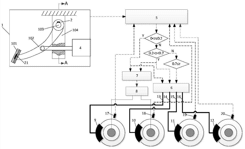
[0022] Such as Figure 1a , Figure 1b Shown is a schematic diagram of the overall structure of the present invention. The electric vehicle brake-by-wire system includes a brake control mechanism 1, a pedal angular displacement sensor 2, a torsion spring 3, a pedal feeling simulator 4, an electro-hydraulic composite brake control unit 5, a hydraulic control unit 6, a motor control unit 7, and an electric motor 8 , left front brake 9, right front brake 10, left rear brake 11, right rear brake 12, hydraulic brake pipelines 13, 14, 15, 16, four wheel speed sensors 17, 18, 19, respectively arranged on each wheel 20 and pedal force sensor 21.

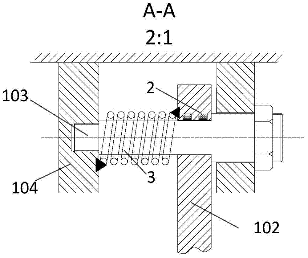
[0023] Such as Figure 1a , Figure 1b shown. The brake operating mechanism of the electric vehicle brake-by-wire system includes a brake pedal 101 , a pedal operating arm 102 , a pedal shaft 103 and a ...


PUM


Abstract

The invention relates to a line control brake system pedal force simulation and a braking force control system of an electric car. The braking force control system comprises a braking operation mechanism, a pedal feel simulator, torsion springs, a pedal angular displacement sensor, a pedal force sensor and an electro-hydraulic composite braking control system. A pedal operating arm of the braking operation mechanism is connected with the front end of a push bar of the pedal feel simulator through hinge rotation. The torsion spring are loosely sleeved on a pedal shaft of the braking operation mechanism, one end of the pedal shaft is fixedly connected on a pedal fixing support, and the other end of the pedal shaft is fixedly connected with the pedal operating arm. The pedal angular displacement sensor is mounted in a round hole of the upper end of the pedal operating arm. The pedal force sensor is mounted on the braking pedal. Pedal angular displacement sensor signals and pedal force sensor signals are input to a control unit of the electro-hydraulic composite braking control system. By the aid of the braking force control system, feeling of a braking pedal can be simulated, a good response is brought to acting force of the pedal, and braking forces of front and rear shafts of the electric car are controlled by identifying braking intention of a driver and calculating braking intensity.

Description

technical field [0001] The invention relates to a pedal force simulation and braking force control system of an electric vehicle by wire brake system, in particular to a pedal force simulation and braking force distribution and control system of a wire control electro-hydraulic composite brake system suitable for pure electric vehicles or hybrid vehicles A control system belongs to the technical field of automobile manufacturing. Background technique [0002] When a traditional fuel vehicle brakes, the braking energy is lost in the form of heat through the friction of the brakes, and the braking energy cannot be recovered. When the electric vehicle brakes, the motor can be converted into a generator for feedback braking, and the braking energy is recovered in the form of electric energy. This measure not only reduces the heat transfer from the car to the environment, but also enables the recovery of braking energy. Therefore, the electric vehicle braking system is an elect...

Claims


Application Information

Patent Timeline
Patent Type & Authority Applications(China)
IPC IPC(8): B60T11/10B60L7/10B60T7/06
Inventor 姬芬竹周晓旭
Owner BEIHANG UNIV
Why Eureka
Try Eureka