Top combustion type hot air furnace arranging annular flameless combustion device below arch roof of combustion chamber

A flameless combustion and combustion chamber technology, applied in brick blast furnaces and other directions, can solve the problems of low combustion temperature, uneven mixing, incomplete combustion, etc., and achieve the effect of reducing environmental pollution, novel and unique structure, and reducing emissions.

Active Publication Date: 2014-01-01
陈维汉
View PDF3 Cites 7 Cited by
  • Summary
  • Abstract
  • Description
  • Claims
  • Application Information

AI Technical Summary

Problems solved by technology

[0003] In view of the above situation, in order to overcome the defects of the prior art, the purpose of the present invention is to provide a top-burning hot blast stove with an annular flameless combustion device under the vault of the combustion chamber, which can effectively solve the problem of low mixing rate of gas and air, and inaccurate mixing. Uniformity, low combustion intensity, low combustion temperature, incomplete combustion, large combustion chamber space and complex burner structure

Method used


Image

  • Top combustion type hot air furnace arranging annular flameless combustion device below arch roof of combustion chamber
  • Top combustion type hot air furnace arranging annular flameless combustion device below arch roof of combustion chamber
  • Top combustion type hot air furnace arranging annular flameless combustion device below arch roof of combustion chamber

Examples


Embodiment Construction

[0009] The specific implementation manners of the present invention will be described in detail below in conjunction with the accompanying drawings.

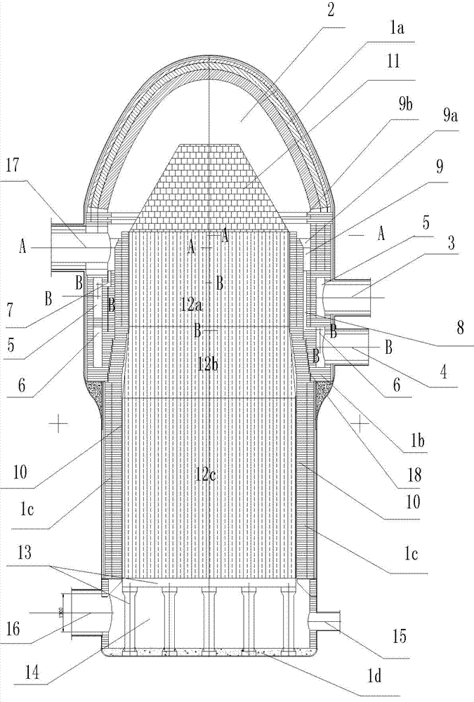
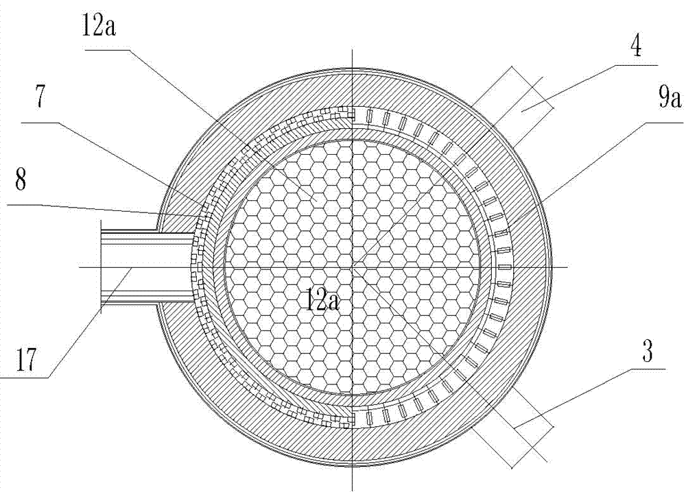
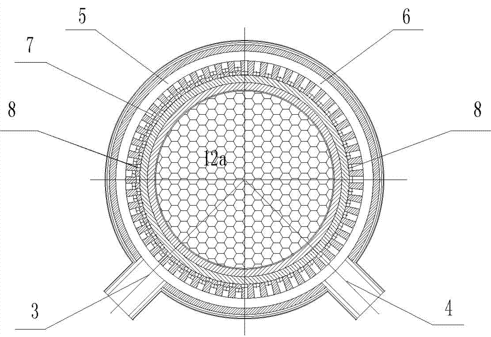
[0010] Such as figure 1 , figure 2 and image 3 As shown, the present invention includes combustion chamber wall 1a, combustion chamber 2, ceramic porous body 11, hot air outlet pipe 17, burner wall 1b, gas intake pipe 3, air intake pipe 4, gas distribution ring 5, air distribution Ring road 6, gas nozzle channel 7, air nozzle channel 8, gas and air premixing ring 9, premixed gas nozzle 9a, jet flow blocking ring 9b, regenerator wall 1c, regenerator 10, porous storage Heat body 12, furnace grate and support column 13, labyrinth connection 18 between regenerator wall and burner wall, furnace bottom 1d, cold air chamber 14, flue gas outlet pipe 16 and cold air inlet pipe 15, combustion chamber wall The body 1a is in the shape of a spherical vault, and its inner cone is stacked with combustion-supporting ceramic porous bodies 1...


PUM


Abstract

The invention relates to a top combustion type hot air furnace arranging an annular flameless combustion device below an arch roof of a combustion chamber, which is used for solving the problems of low mixing rate of coal gas and air and low combustion intensity. The structure is as follows: a wall body of the combustion chamber is shaped like the spherical arch roof, a combustion-supporting ceramic porous body is arranged in the wall body of the combustion chamber, the wall body of the combustion chamber and the wall body of a combustor at the lower part are connected into a whole, a coal gas inlet pipe and an air inlet pipe on the wall body of the combustor are built on a coal gas distribution ring path and an air distribution ring path, a pre-mixed gas spout is arranged at the upper part of a coal gas and air pre-mixing ring path, and a gas flow blocking ring is arranged above the pre-mixed gas spout; and a hot air outlet pipe is arranged on the wall body of the combustor, the inner side of a lower cylindrical body and the outer side of an inner-layer cylindrical wall body at the upper part of the wall body of a heat accumulation chamber are mutually sheathed and connected in a slippage manner via a ladder joint type labyrinth hermetic connection structure, a porous heat accumulation body is arranged in the heat accumulation chamber, a cold air chamber is constituted between the wall body of the heat accumulation chamber at the lower part of a furnace grate and the bottom of the furnace, and a flue gas outlet pipe and a cold air inlet pipe are arranged on the wall body of a cold air chamber. The top combustion type hot air furnace provided by the invention can save fuel and reduce the temperature of waste gas and the emission of harmful gas.

Description

technical field [0001] The invention relates to a hot blast stove, in particular to a top-combustion hot blast stove with an annular flameless combustion device under the vault of a combustion chamber for providing high-temperature blast for a blast furnace. Background technique [0002] At present, considering energy saving and consumption reduction, blast furnace hot blast stoves are required to obtain high performance and high blast temperature under the combustion of low calorific value blast furnace gas, and finally achieve the goals of high efficiency, energy saving, environmental protection, and increased production. For this reason, an optimized combustion process must be combined with an enhanced heat transfer process in the hot blast stove. This involves the structure of the combustion device, the structure and arrangement of the heat storage body, and the organization of the air flow field. Looking at the various hot blast stoves currently in use, their gas combu...

Claims


Application Information

Patent Timeline
Patent Type & Authority Applications(China)
IPC IPC(8): C21B9/04
Inventor 陈维汉陈云鹤杨海涛
Owner 陈维汉
Why Eureka
Try Eureka