Trough beam

A groove-shaped beam and groove-shaped technology, applied in the direction of joists, girders, truss beams, etc., can solve the problems of unsafe, large space occupation, poor installation stability, etc. powerful effect

Active Publication Date: 2014-01-01
GUANGSHA CHONGQING FIRST CONSTR GROUP
View PDF10 Cites 0 Cited by
  • Summary
  • Abstract
  • Description
  • Claims
  • Application Information

AI Technical Summary

Problems solved by technology

[0004] The invention provides a channel beam to solve the problems of large space occupied by building infrastructure, poor installation stability and unsafety in existing building floors

Method used


Image

  • Trough beam
  • Trough beam
  • Trough beam

Examples


Embodiment Construction

[0016] Below in conjunction with accompanying drawing and specific embodiment the present invention will be described in further detail:

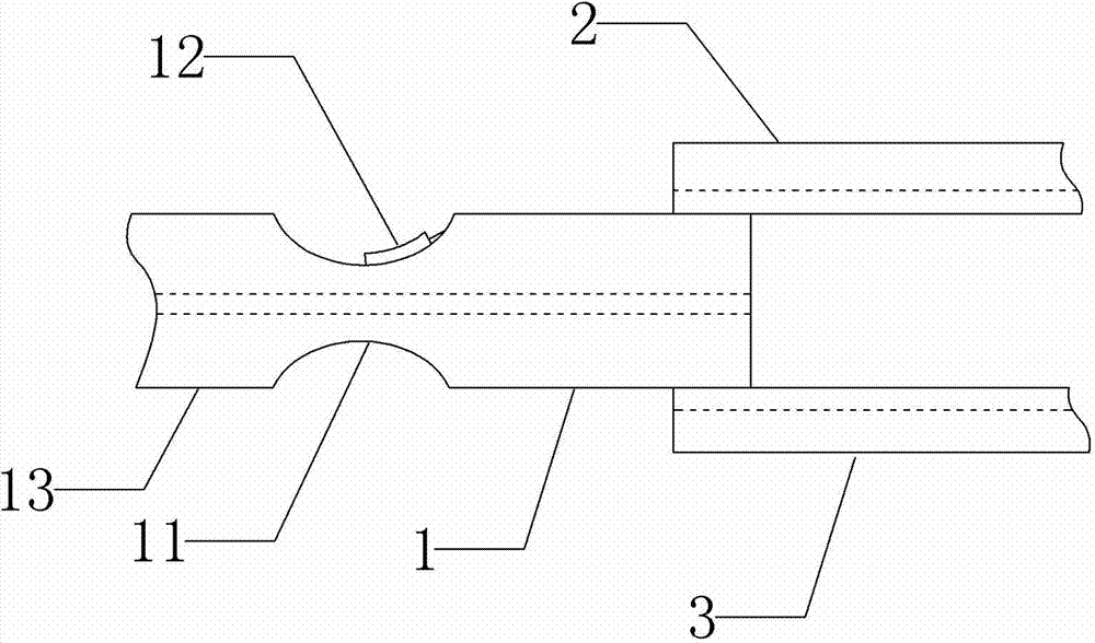
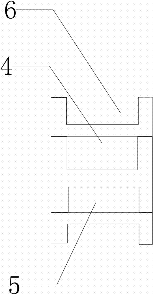
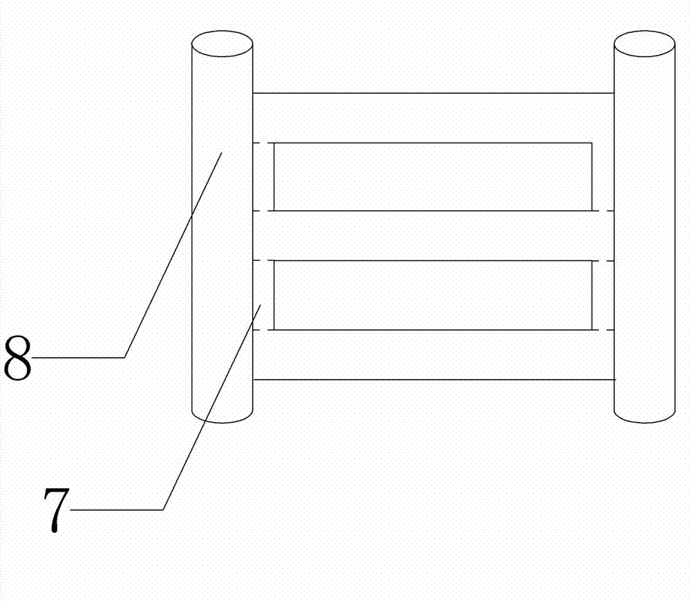
[0017] Such as figure 1 , figure 2 Shown is the schematic diagram of the channel beam of this embodiment, the channel beam includes a main beam 1, the main beam 1 is an I-shaped beam, one side of the main beam 1 is provided with a first side beam 2, and the other side of the main beam 1 A second side beam 3 is provided, the lengths of the first side beam 2 and the second side beam 3 are smaller than the length of the main beam, the widths of the main beam 1, the first side beam 2 and the second side beam 3 are equal, and the main beam 1 and the first side beam 2 form a first grooved channel 4 along the length direction of the main beam, a second grooved channel 5 is formed between the main beam 1 and the second side beam 3 along the length direction of the main beam, and the first side beam 2 and the second side beam 3 are provided with ...


PUM


Abstract

The invention discloses a trough beam for solving the problems that the building infrastructures of the conventional building floors occupy large space, and are poor in mounting stability and unsafe. The trough beam comprises a girder, wherein the girder is arranged between building uprights; the girder is I-shaped, a first side beam is arranged on one side of the girder, and a second side beam is arranged on the other side of the girder; the girder, the first side beam and the second side beam are the same in width; a first trough channel is formed between the girder and the first side beam in the length direction of the girder; a second trough channel is formed between the girder and the second side beam in the length direction of the girder. Compared with the hanging mounting of the conventional hanging pieces, the trough beam has the advantages that the building infrastructures can be centralized in the trough channels, space occupied by each infrastructure can be effectively reduced, various building infrastructures are centralized in the trough channels, and the safety of the building infrastructures can be improved; meanwhile, due to the structure of the trough beam, the carrying capacity of the trough beam is larger, so that the mounting stability of the each infrastructure can be ensured.

Description

technical field [0001] The invention relates to a frame beam structure for building, in particular to a channel beam. Background technique [0002] Frame beams refer to beams whose two ends are connected to building frame columns, or beams whose two ends are connected to shear walls but the span-to-height ratio is not less than five. Frame beams can be divided into: roof frame beams, roof frame beams refer to the frame beams at the highest part of the frame structure roof; floor frame beams, floor frame beams refer to frame beams on each floor; underground frame beams, underground frame beams refer to It is set above the top surface of the foundation and below the positive and negative zero of the building elevation and is supported by frame columns, and is not affected by the reaction force of the foundation, or the reaction force of the foundation is only produced by the self-weight of the underground beam and its covering soil, not by the upper load The effect of such...

Claims


Application Information

Patent Timeline
Patent Type & Authority Applications(China)
IPC IPC(8): E04C3/02
Inventor 陈阁琳于庭伟卢光火欧阳宁静杨玺潘颖田驰
Owner GUANGSHA CHONGQING FIRST CONSTR GROUP
Why Eureka
Try Eureka