Bracket type overhanging scaffold and construction method thereof at erection time

A technology of cantilevered scaffolding and corbels, which is applied to the accessories of scaffolding, scaffolding supported by house structure, construction, etc., can solve the problems affecting the structural stability of cast-in-place slabs, reducing the strength of shear walls, etc. Construction progress, cost saving effect

Active Publication Date: 2014-01-01
四川省第四建筑有限公司
View PDF7 Cites 5 Cited by
  • Summary
  • Abstract
  • Description
  • Claims
  • Application Information

AI Technical Summary

Problems solved by technology

Most of the anchor points of the existing cantilevered steel beams are set on the cast-in-place slab. Under the gravity of the scaffolding, each anchor point has a force of about 10KN to pull the cast-in-place slab upward. Such concentrated load will affect the cast-in-place slab structure. the stability of
When the existing cantilevered steel beam passes through the shear wall, a hole of 200mm*250mm needs to be left on the shear wall, which will reduce the strength of the shear wall by 10% in the horizontal section

Method used


Image

  • Bracket type overhanging scaffold and construction method thereof at erection time
  • Bracket type overhanging scaffold and construction method thereof at erection time
  • Bracket type overhanging scaffold and construction method thereof at erection time

Examples


Embodiment 1

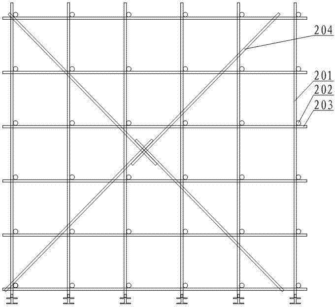
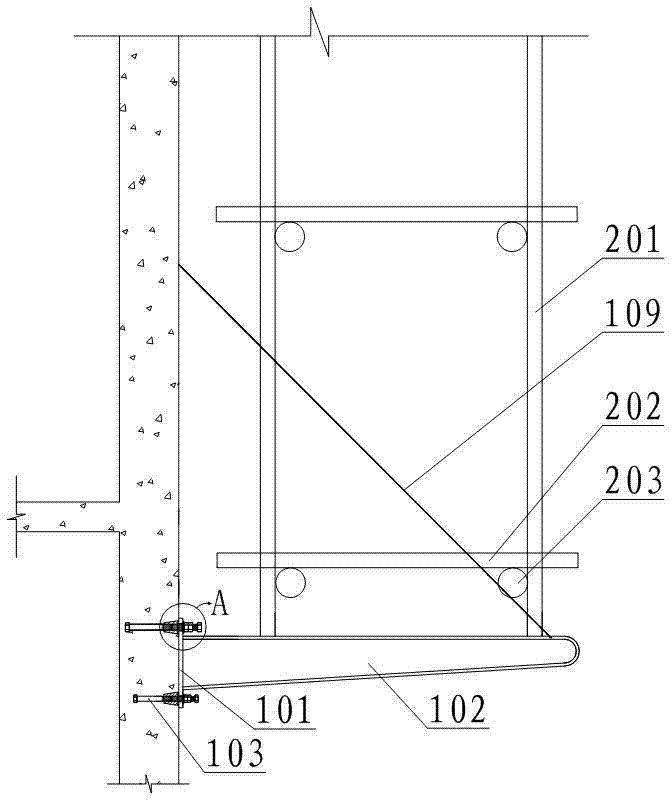
[0031] Such as figure 1 and figure 2 As shown, the corbel-type cantilevered scaffold includes scaffolding and a plurality of cantilevered support seats, wherein the plurality of cantilevered support seats are connected at the same level of the shear wall and distributed at equal intervals in the longitudinal direction. The cantilever support seat includes a connecting plate 101, a steel beam 102, a threaded connector 103 and an outer limit nut 104. One end of the steel beam 102 is connected to the end surface of the connecting plate 101 and is perpendicular to the connecting plate 101, and one end of the threaded connector 103 passes through the connecting plate. The plate 101 is embedded in the shear wall, the outer limit nut 104 is provided with an internal thread matching the external thread of the threaded connector 103, the outer limit nut 104 is sleeved on the threaded connector 103, and the connecting plate 101 is located between the shear wall and the Between the out...

Embodiment 2

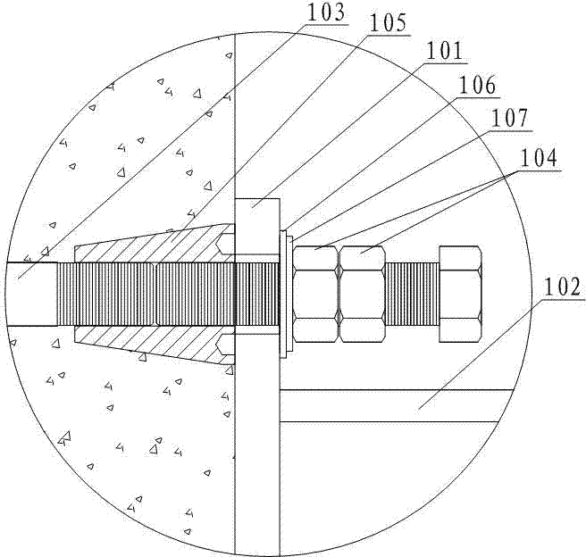
[0036] Such as image 3 As shown, the present embodiment has the following improvements on the basis of Embodiment 1: the cantilever bearing seat of this embodiment also includes a tapered sleeve 105, a flat washer 106 and an elastic washer 107, wherein the tapered sleeve 105. The end face of the end with the larger diameter is flush with the outer wall surface of the shear wall, and the end face is concave to form an annular groove. The tapered sleeve 105 is provided with an internal thread that matches the external thread of the threaded connector 103. The tapered sleeve 105 is located in the shear wall and is connected to the threaded connector 103 by thread matching. The flat gasket 106, elastic pad The pieces 107 are all sleeved on the threaded connector 103 and located between the connecting plate 101 and the outer limit nut 104, the flat washer 106 is in contact with the connecting plate 101, and the two ends of the elastic washer 107 are in contact with the flat washer...

Embodiment 3

[0038] This embodiment is improved as follows on the basis of Embodiment 2: the threaded connector 103 of this embodiment uses two bolts, one bolt is located inside the shear wall, and the head of the other bolt is located outside the shear wall, The other ends of the two bolts opposite to the head end are embedded in the tapered sleeve 105 and connected with the tapered sleeve 105 . In this way, when this embodiment is applied, the cantilevered support seat is fixed or disassembled by adjusting the bolt whose head is located outside the shear wall.


PUM


Abstract

The invention discloses a bracket type overhanging scaffold which comprises a scaffold body and a plurality of overhanging supporting seats. Each overhanging supporting seat comprises a connecting plate, a threaded connecting piece, and an outer limiting nut arranged on the threaded connecting piece in a sleeved mode, wherein one end of the threaded connecting piece is connected with an upper steel beam on the end face of the connecting plate, the other end of the threaded connecting piece penetrates through the connecting plate and is embedded into a shear wall, and the connecting plate is located between the shear wall and the outer limiting nut. The scaffold body comprises transverse horizontal rods, longitudinal horizontal rods and a plurality of rows of vertical rod sets. Each row of vertical rod sets comprises vertical rods the same as the overhanging supporting seats in number. The vertical rods in each row of vertical rod sets are arranged on steel beams in a one-to-one correspondence mode. A plurality of vertical rods arranged on the same steel beam are connected with one another through a plurality of transverse horizontal rods. A plurality of vertical rods in each row of vertical rod set are connected with one another through a plurality of longitudinal horizontal rods. The invention further discloses a construction method for the bracket type overhanging scaffold. The bracket type overhanging scaffold is simple in structure, convenient to install and detach, and has little influence on the strength of a building structure at utilization time.

Description

technical field [0001] The invention relates to the field of building construction, in particular to a corbel-type cantilevered scaffold and a construction method during erection thereof. Background technique [0002] With the rapid development of urban construction, the number of high-rise and super high-rise buildings is increasing, and the construction environment is becoming more and more complex. In order to meet the needs of structural construction and exterior decoration construction, people generally use cantilevered steel beams to support scaffolding. Most of the anchor points of the existing cantilevered steel beams are set on the cast-in-place slab. Under the gravity of the scaffolding, each anchor point has a force of about 10KN to pull the cast-in-place slab upward. Such concentrated load will affect the cast-in-place slab structure. of stability. When the existing cantilevered steel beam passes through the shear wall, a hole of 200mm*250mm needs to be left in ...

Claims


Application Information

Patent Timeline
Patent Type & Authority Applications(China)
IPC IPC(8): E04G3/18E04G5/04E04G5/16
Inventor 颜有光杨洪李林钟浩
Owner 四川省第四建筑有限公司
Why Eureka
Try Eureka