Vertical reinforcement connection method of prefabricated hollow concrete composite shear wall

A technology of hollow concrete and laminated shear walls, which is applied in the fields of construction, building structure, and building material processing, can solve problems such as inconvenient operation, achieve reliable connection, and speed up construction

Active Publication Date: 2015-08-12
凡林装配式建筑科技有限公司
View PDF8 Cites 5 Cited by
  • Summary
  • Abstract
  • Description
  • Claims
  • Application Information

AI Technical Summary

Problems solved by technology

The mechanical connection and welding are the same as the traditional concrete structure construction method, and the operation is inconvenient

Method used


Image

  • Vertical reinforcement connection method of prefabricated hollow concrete composite shear wall
  • Vertical reinforcement connection method of prefabricated hollow concrete composite shear wall
  • Vertical reinforcement connection method of prefabricated hollow concrete composite shear wall

Examples


specific Embodiment 1

[0026] Specific embodiment 1 (standard floor position)

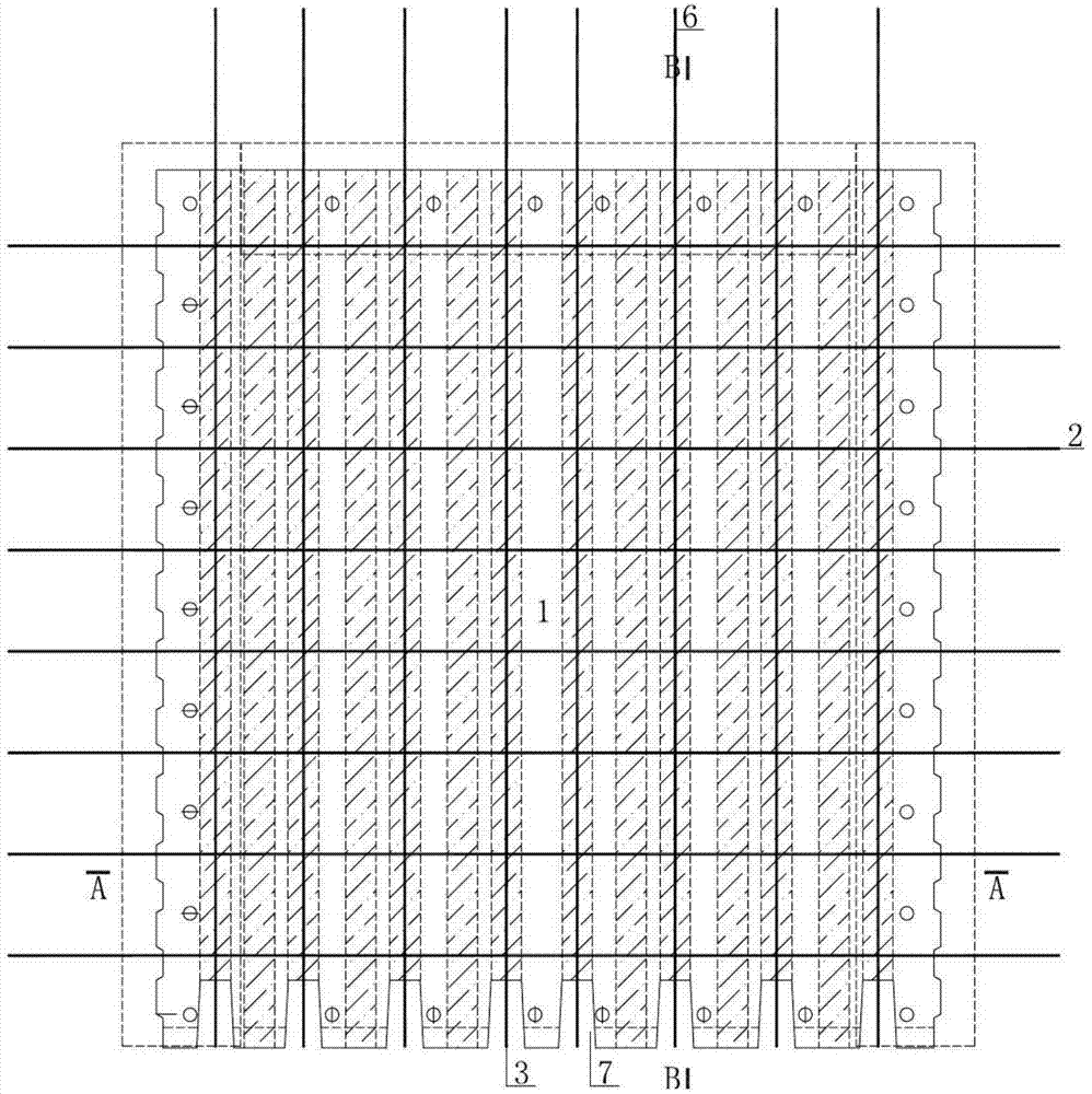
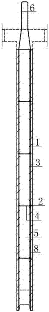
[0027] Step 1. At the end of the prefabricated shear wall member 1, reserve the vertical reinforcing bar 3 of the member to the upper part. The throwing length ranges from 15d to 40d, where d is the diameter of the vertical steel bars 3 of the component, and the spacing of the vertical external steel bars 6 of the component is the same as that of the vertical steel bars 3 of the component, which is 100mm to 300mm;

[0028] Step 2, the lower part of the prefabricated shear wall member 1 is provided with an installation slot 7;

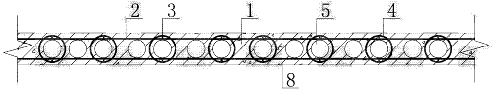
[0029] Step 3, the vertical reinforcing bars 3 of the component are located on both sides of the vertical hollow hole 5 of the component, and the vertical reinforcing bar 3 of the component bypasses the vertical hollow hole 5 of the component through the circular tie reinforcing bar 4 of the component to realize the tie;

[0030] Step 4. First, the vertical hollow hole 5 of the upper prefabricate...

specific Embodiment 2

[0032] Specific embodiment 2 (top level position)

[0033] Step 1. At the end of the prefabricated shear wall component 1, reserve the vertical reinforcement 3 of the prefabricated component to the upper part. When it is the top floor of a floor, the length of the prefabricated vertically thrown steel bars 6 is the top elevation of the floor roof minus 20mm, and the distance between the vertically thrown steel bars 6 of the prefabricated components is the same as that of the vertical steel bars 3 of the prefabricated components, which is 100mm ~300mm;

[0034] Step 3, the prefabricated component is anchored in the cast-in-place beam at the elevation of the top floor;

[0035] Step 4: By pouring concrete 9 into the hollow part of the prefabricated shear wall component 1, the installation of the prefabricated shear wall component 1 is completed, so that the prefabricated shear wall component 1 forms a whole.


PUM


Abstract

The invention discloses a vertical steel bar connection method for a prefabricated hollow concrete laminated shear wall, which belongs to the field of building concrete structure engineering. Step 1. Throw out the vertically distributed steel bars in the shear wall components upwards, reserve the outer steel bars, and set slot holes in the lower part of the components to facilitate the overlapping connection of the steel bars when the upper and lower members are installed and docked; Step 2, the components The upper externally thrown steel bars pass through the floor position during installation; step 3, insert the vertical holes of the corresponding hollow concrete shear wall members of the upper layer, and insert the externally thrown steel bars of the shear wall members of the next layer into the holes. At the position of the installation slot hole, the external steel bar is lapped and connected with the vertical steel bar in the component; step 4, the concrete in the hollow part is poured into the core to complete the installation of the component, so that the component forms a whole. The invention makes the connection of the vertical reinforcement of the assembled hollow concrete shear wall simple, the quality is easy to guarantee, the productivity is improved, the building quality can be guaranteed and the construction cost can be reduced.

Description

technical field [0001] The invention belongs to the field of building concrete structure engineering, in particular relates to a prefabricated concrete structure, and is an improvement to the current prefabricated concrete structure design and construction method. Background technique [0002] Housing industrialization is the development trend of modern housing construction. Prefabricated shear wall structure is the most widely used structural form in residential buildings. [0003] At present, the methods for assembling the vertical reinforcement of integral shear wall structures mainly include: reinforcement sleeve grouting connection, indirect lap connection, mechanical connection or welding, etc. Please refer to the sixth issue of the paper "Development and Application of Key Technologies of Prefabricated Concrete Structures Abroad" published in the journal "Residential Industry" in 2011. The author of this article is Li Xiaoming. The sleeve connection needs to connec...

Claims


Application Information

Patent Timeline
Patent Type & Authority Patents(China)
IPC IPC(8): E04G21/14E04G21/12
Inventor 孟凡林孟祥瑞付萍孟锦
Owner 凡林装配式建筑科技有限公司
Why Eureka
Try Eureka