
Hydraulic equilibrium debugging device of heating and ventilating system and debugging method thereof

A technology of hydraulic balance and debugging method, which is applied in the direction of heating system, heating method, space heating and ventilation, etc., can solve problems such as complex debugging process, uneven heating and cooling, poor heating quality, etc., and achieve high adjustment accuracy, The effect of high regulation efficiency

Inactive Publication Date: 2014-01-01
卓旦春
View PDF3 Cites 11 Cited by
  • Summary
  • Abstract
  • Description
  • Claims
  • Application Information

AI Technical Summary

Problems solved by technology

However, the basis and necessary condition of the on-off time area method is the hydraulic balance of the heating system. Due to the unbalanced flow among households, the gap between the heat consumption effect and the heat charge between users will be 20%-30%, which will cause Poor heating quality, uneven heating and cooling, unreasonable heat metering and difficulty in charging
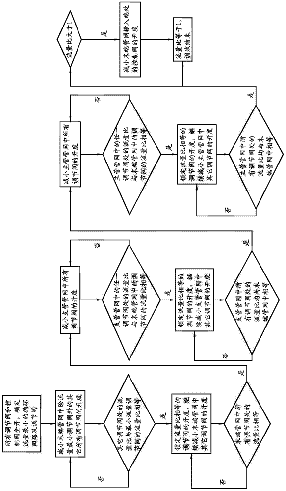
[0004] At present, the hydraulic balance debugging methods for HVAC systems include proportional method, compensation method, etc. Although all of them can carry out hydraulic balance debugging, the debugging process is complicated and time-consuming.

Method used


Image

  • Hydraulic equilibrium debugging device of heating and ventilating system and debugging method thereof
  • Hydraulic equilibrium debugging device of heating and ventilating system and debugging method thereof

Examples


Embodiment Construction

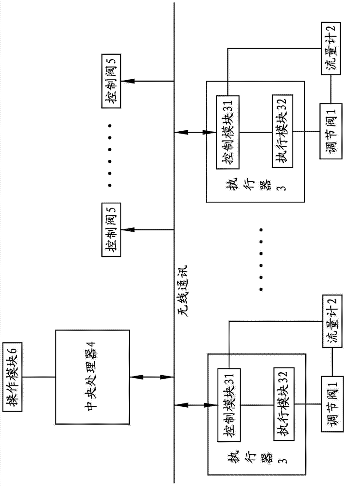
[0027] The following are specific embodiments of the present invention and in conjunction with the accompanying drawings, the technical solutions of the present invention are further described, but the present invention is not limited to these embodiments.

[0028] The HVAC system hydraulic balance debugging device is used to debug the hydraulic balance of each circulation loop in the HVAC system. The HVAC system includes a main pipe network, a branch pipe network and several terminal pipe networks that can form their own circulation loops. The main pipe network is used to communicate with the heat station, and the main pipe network, branch pipe network and end pipe network are respectively connected through heat exchangers or directly connected.

[0029] like figure 1 As shown, the HVAC system hydraulic balance debugging device includes a number of regulating valves 1 respectively connected to each circulation loop in the main pipe network, branch pipe network and terminal pi...


PUM


Abstract

The invention provides a hydraulic equilibrium debugging device of a heating and ventilating system and a debugging method thereof, which are used for solving a problem that the hydraulic equilibrium debugging process in an existing heating and ventilating system is complex. According to the hydraulic equilibrium debugging device of the heating and ventilating system, the heating and ventilating system comprises a main-pipe pipe network, a branch-pipe pipe network and a plurality of tail-end pipe networks, wherein the main-pipe pipe network is to be communicated with a heating station; the main-pipe pipe network, the branch-pipe pipe network and the tail-end pipe networks are respectively communicated, correspondingly; the debugging device comprises a plurality of regulating valves, flow rate meters, an actuator and a central processor, wherein the plurality of regulating valves are correspondingly connected in a circulation loop formed by the main-pipe pipe network, the branch-pipe pipe network and the tail-end pipe networks, respectively; the flow rate meters are respectively arranged on the regulating valves and used for detecting the flow rates of the regulating valves; the actuator is connected to the regulating valves and used for controlling the regulating valves to act; and the central processor can be used for receiving a flow rate signal sent by the flow rate meters and driving the actuator to adjust the degree of opening of the regulating valves according to the flow rate signal. The hydraulic equilibrium debugging device of the heating and ventilating system and the debugging method thereof disclosed by the invention have the advantages of high debugging efficiency and high debugging precision.

Description

technical field [0001] The invention relates to a hydraulic balance debugging device and a debugging method for a HVAC system. Background technique [0002] The structure of the HVAC system generally includes a primary pipe network that is connected to the thermal station and forms a circulation loop, a heat exchanger, and a secondary pipe network that forms a circulation loop. The primary pipe network and the secondary pipe network pass through the heat exchanger connected. There are several user ends on the secondary pipe network, and each user end has a regulating valve. In order to meet the heat supply needs of more users, a tertiary pipe network that can form a circulation loop can also be connected in parallel on the primary pipe network and / or the secondary pipe network. There are several user terminals connected in parallel on the tertiary pipe network, and each user end Both have regulating valves and the access end of the tertiary pipe network has control valves....

Claims


Application Information

Patent Timeline
Patent Type & Authority Applications(China)
IPC IPC(8): F24D19/10
Inventor 卓旦春
Owner 卓旦春
Learn More