Single-fiber bi-directional light receiving and emitting device

A bidirectional light and device technology, applied in the field of optical communication, can solve the problems of complex structure, difficult installation, high cost, etc., and achieve the effect of reasonable structure, reduced production cost, simple and compact components

Active Publication Date: 2014-01-01
INST OF SEMICONDUCTORS - CHINESE ACAD OF SCI
View PDF5 Cites 8 Cited by
  • Summary
  • Abstract
  • Description
  • Claims
  • Application Information

AI Technical Summary

Problems solved by technology

This design of the prior art has disadvantages such a...

Method used


Image

  • Single-fiber bi-directional light receiving and emitting device
  • Single-fiber bi-directional light receiving and emitting device
  • Single-fiber bi-directional light receiving and emitting device

Examples


Embodiment Construction

[0024] In order to make the object, technical solution and advantages of the present invention clearer, the present invention will be described in further detail below in conjunction with specific embodiments and with reference to the accompanying drawings.

[0025] In order to make the purpose, technical scheme and advantages of the present invention clearer, the present invention will be described in further detail below with reference to the accompanying drawings, in order to understand the structure and working process of the present invention more clearly, but it cannot be used to limit the scope of the present invention. protected range.

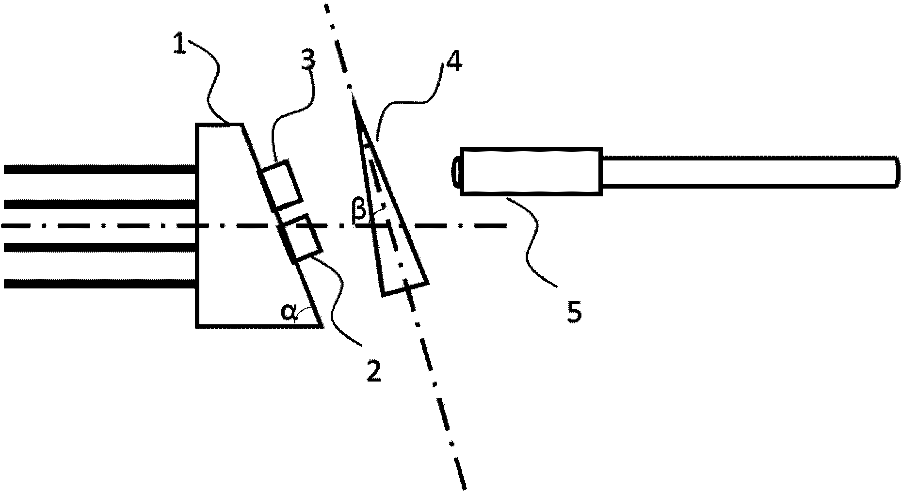
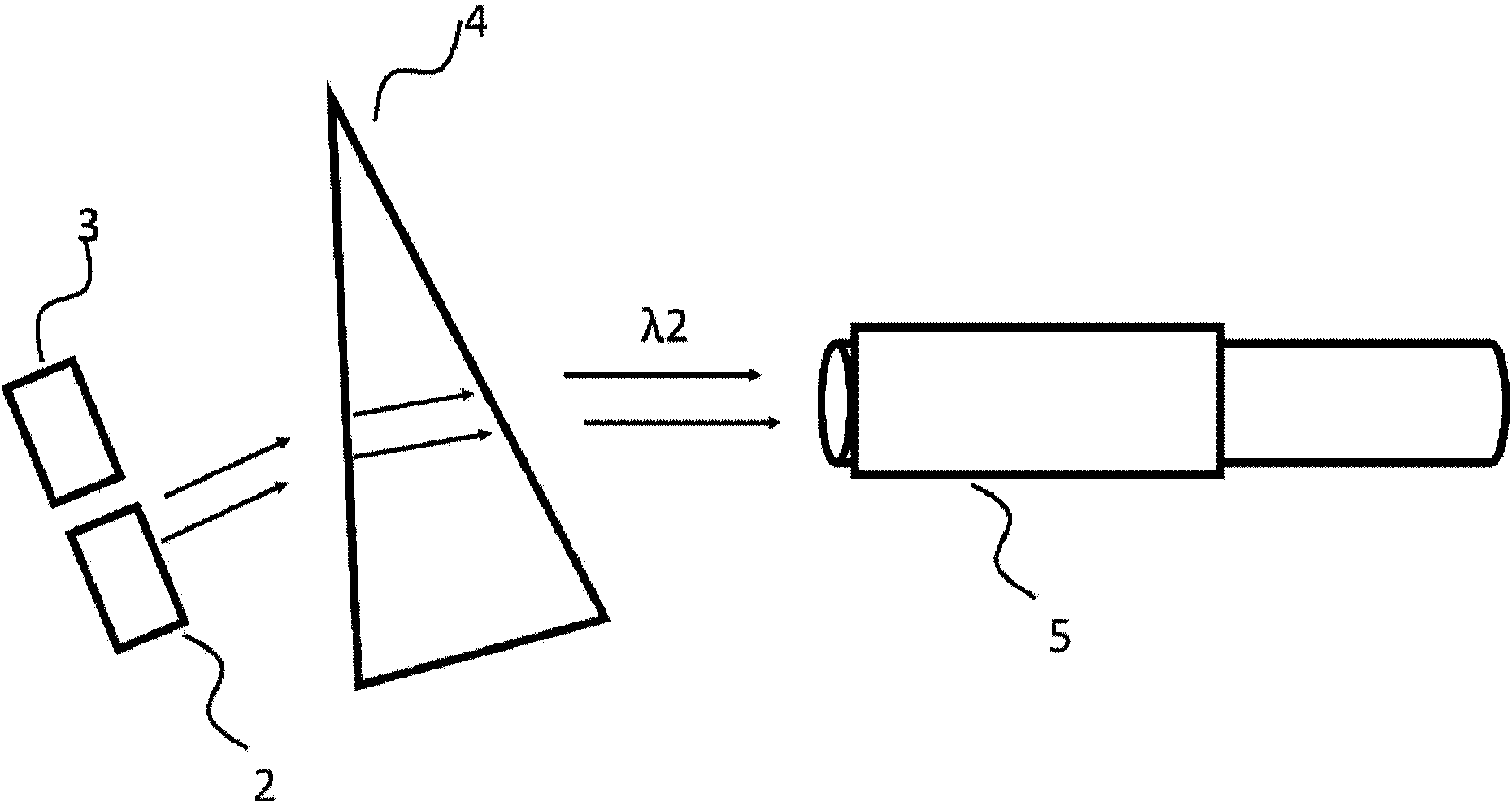
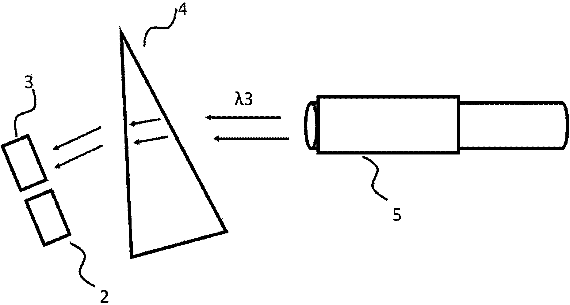
[0026] Such as figure 1 As shown, the single-fiber bidirectional optical transceiver device provided by the present invention includes: a TO socket 1, a laser 2 encapsulated in a TO shell, a detector 3 encapsulated in a TO shell, a lens grating of unequal thickness 4 and an optical fiber connection device 5. The cut surface of the TO...


PUM


Abstract

The invention discloses a single-fiber bi-directional light receiving and emitting device which comprises a TO tube socket, a laser device encapsulated in a TO tube shell, a detector encapsulated in the TO tube shell, lenticulation with different thicknesses and an optical fiber connector. The cross section of the TO tube socket is of a right trapezoid, the right angle surface of the TO tube socket is connected with TO base pins, and the direction of the base pins is parallel to the axial direction of the TO tube shell. The laser device and the detector are welded on the inclined plane of the TO tube socket and are arranged in parallel, and electrode leading wires are led to the base pins from the inclined plane of the tube socket through the whole TO tube socket and are connected with the base pins. The lenticulation with different thicknesses is arranged and fixed obliquely, and the intersection angle between the lenticulation with different thicknesses and the axial direction of the TO tube shell is beta. The laser device emits optical signals, and the optical signals are refracted through the lenticulation with different thicknesses and enter an optical fiber in the optical fiber connector. External light enters the single-fiber bi-directional light receiving and emitting device through the optical fiber, and enters the detector through the refraction of the lenticulation with different thicknesses. Through the utilization of the single-fiber bi-directional light receiving and emitting device, cost is saved, and the welding and mounting of BOSA modules are made to be convenient at the same time.

Description

technical field [0001] The invention relates to the technical field of optical communication, in particular to a single-fiber bidirectional optical transceiver device for optical communication transmission. Background technique [0002] Optical communication technology has become the most important pillar of modern communication and plays a mainstay role in modern communication. At the same time, as an emerging technology that is gradually becoming mature, optical communication has developed rapidly in recent years, which is rare in the history of communication. Optical communication is destined to become the main transmission tool for various information in the future information society. [0003] Single-fiber bidirectional optical transceiver device (Bi-direction Optic Sub-assembly, referred to as BOSA) is a photoelectric conversion device that integrates transmitting and receiving. It can realize the function of bidirectional transmission of data in a single optical fibe...

Claims


Application Information

Patent Timeline
IPC IPC(8): G02B6/42H04B10/40
Inventor 刘宇常明超祝宁华
Owner INST OF SEMICONDUCTORS - CHINESE ACAD OF SCI
Why Eureka
Try Eureka