
An Arbitrary Waveform Generating System and Method

An arbitrary waveform and generation system technology, applied in the direction of digital function generators, etc., can solve the problems of insufficient diversity of signal styles, influence of waveform download speed and external interface speed, and few signal styles, etc.

Inactive Publication Date: 2016-04-27
THE 41ST INST OF CHINA ELECTRONICS TECH GRP
View PDF4 Cites 5 Cited by
  • Summary
  • Abstract
  • Description
  • Claims
  • Application Information

AI Technical Summary

Problems solved by technology

These two methods have their own advantages and disadvantages. Compared with the waveform playback method, the bandwidth realized by the real-time method is smaller, but the signal style can be changed in various ways; the waveform playback method can only generate the waveform existing in the memory. The local bus calls the hard disk data or calls the data of the external counting machine through the external interface, so the waveform download speed and the speed of the external interface are affected by the bandwidth and rate of the instrument's local bus
[0004] In existing instruments and equipment, such as Agilent's 33250, which uses single trigger and cyclic trigger, sequence trigger and combination trigger are not used, and it cannot output phase continuous multi-segment waveforms; R&S's AFQ100A / B only uses single trigger, cyclic trigger Trigger and combined trigger functions, the output signal styles are not diverse enough; Tek’s AWG7122C uses single trigger, cycle trigger, and burst trigger, but does not use sequence trigger, combined trigger, etc., and cannot output multi-segment waveforms with different time gaps
[0005] There are not many signal styles in the existing function generators and arbitrary waveform generators, such as half-cycle, full-cycle, quarter-cycle signals, arbitrary one-cycle signals, etc., there are few types of triggers, and in certain The sampling rate is not variable in triggering, etc.

Method used


Image

  • An Arbitrary Waveform Generating System and Method
  • An Arbitrary Waveform Generating System and Method
  • An Arbitrary Waveform Generating System and Method

Examples


Embodiment Construction

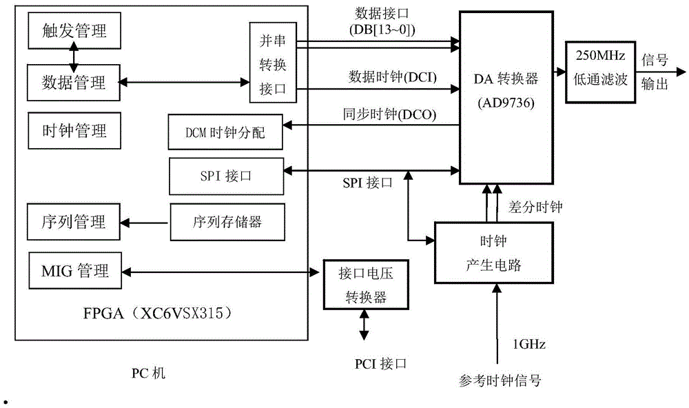
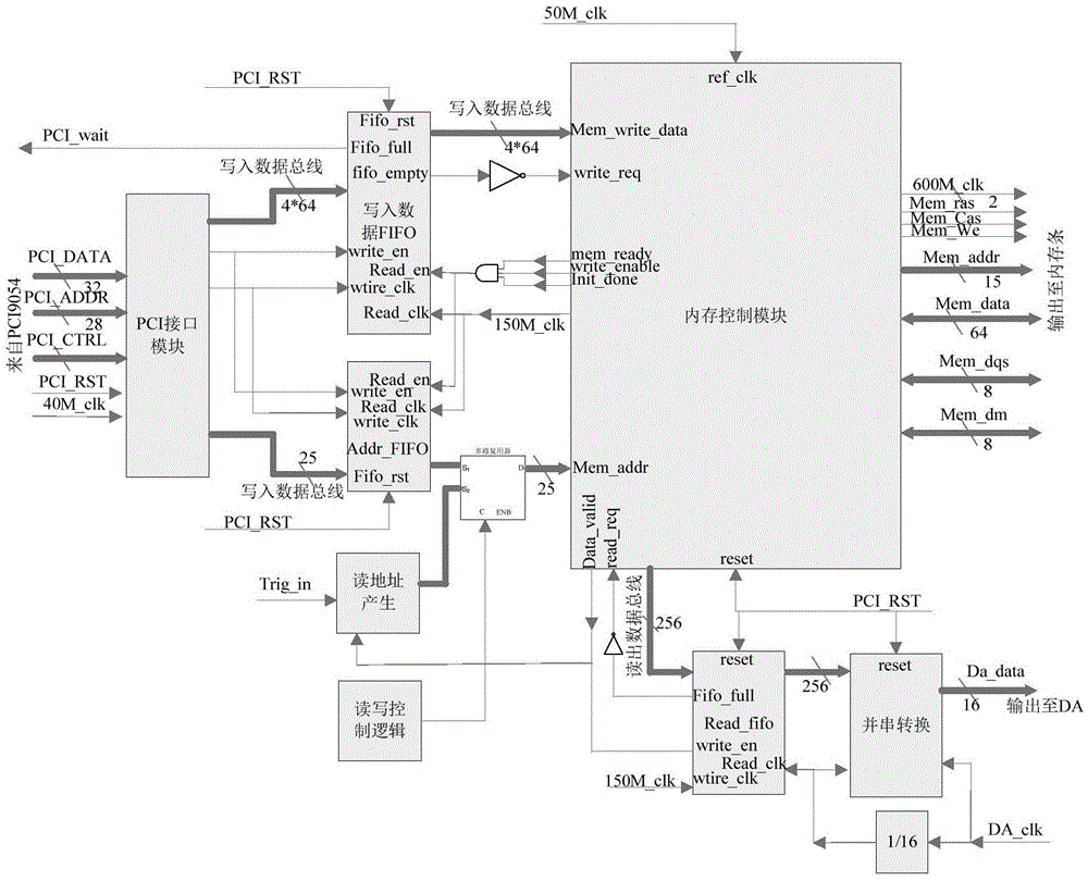
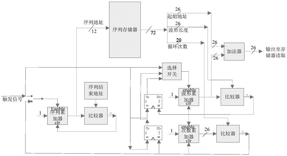
[0055] to combine figure 1 , figure 2 and image 3 , The hardware components involved in the present invention may include: FPGA (model XC6VSX315t), PC (host computer or external computer), DA converter (AD9736), low-pass filter, clock generation circuit and interface voltage converter. The above-mentioned FPGA is provided with a parallel-to-serial conversion interface, a DCM clock distributor, an SPI interface, a sequence memory, a trigger management module, a clock management module, a data management module and a sequence management module. The PC is connected to the FPGA through the PCI interface and the interface voltage converter, the FPGA is connected to the DA converter through the parallel-serial conversion interface, the SPI interface and the DCM clock distributor, the clock generation circuit is connected to the FPGA and the DA converter respectively, and the DA converter is connected to the low-pass filter device.

[0056] The working principle of the present i...


PUM


Abstract

The invention discloses an arbitrary waveform generation system and method for variable-speed waveform data playback based on complex combined triggering. The system comprises a waveform data storage unit and a trigger mode based waveform editing and trigger playback unit; the trigger mode based waveform editing and trigger playback unit comprises a waveform reading address generation subunit and a complex wave synthesis subunit; the waveform reading address generation subunit comprises a pulse gating module, a trigger module, a trigger reset module, a waveform trigger module, a waveform trigger reset module, a waveform trigger buffer module, a sequence trigger module, a sequence trigger repeating module and a sequence trigger setting module. On the basis of real-time digital signal processing, complex combined trigger and variable-speed waveform data playback technologies, the system and method gives full play to the characteristics of all-digital waveform synthesis, high resolution, good signal stability, many signal styles, various modulation and the like, and has the advantages of quick switching, capability of changing length of signal cycles and the like.

Description

technical field [0001] The invention belongs to the field of arbitrary waveform generation, and in particular relates to an arbitrary waveform generation system for variable-rate playback of waveform data triggered by complex combinations, and an arbitrary waveform generation method for variable-rate playback of waveform data triggered by complex combinations. Background technique [0002] Arbitrary waveform generator is a multi-purpose signal excitation source, including FSK, MSK, QAM, PSK and other digital modulation functions, which can generate complex time-varying multi-channel signals and complex modulation signals. With the development of electronic technology, digital baseband modulation signal generation technology has been widely used in various fields such as communication, control, and measurement. Its role in the military is manifested in multiple levels of land, sea, air, and space, high deployment density, multiple spectrum, large time width, large bandwidth, ...

Claims


Application Information

Patent Timeline
IPC IPC(8): G06F1/02
Inventor 陈应兵包思云刘魁魁
Owner THE 41ST INST OF CHINA ELECTRONICS TECH GRP
Learn More