
Hardware driving method suitable for large-sized infrared touch screen

An infrared touch screen, hardware-driven technology, applied in the input/output process of data processing, instruments, electrical digital data processing and other directions, can solve the problems of infrared light signal attenuation, weak signal, affecting the accuracy of coordinate point recognition, etc., to save Power consumption, the effect of avoiding competition and risk

Inactive Publication Date: 2014-01-01
HEFEI UNIV OF TECH
View PDF6 Cites 5 Cited by
  • Summary
  • Abstract
  • Description
  • Claims
  • Application Information

AI Technical Summary

Problems solved by technology

However, as the size increases, the emission distance of the infrared emitting tube increases, and the infrared light signal emitted by it will be attenuated to a greater extent. Coupled with the influence of ambient light, the signal obtained by the infrared receiving tube is very weak, so it will affect Accuracy of coordinate point recognition

Method used


Image

  • Hardware driving method suitable for large-sized infrared touch screen
  • Hardware driving method suitable for large-sized infrared touch screen
  • Hardware driving method suitable for large-sized infrared touch screen

Examples


Embodiment Construction

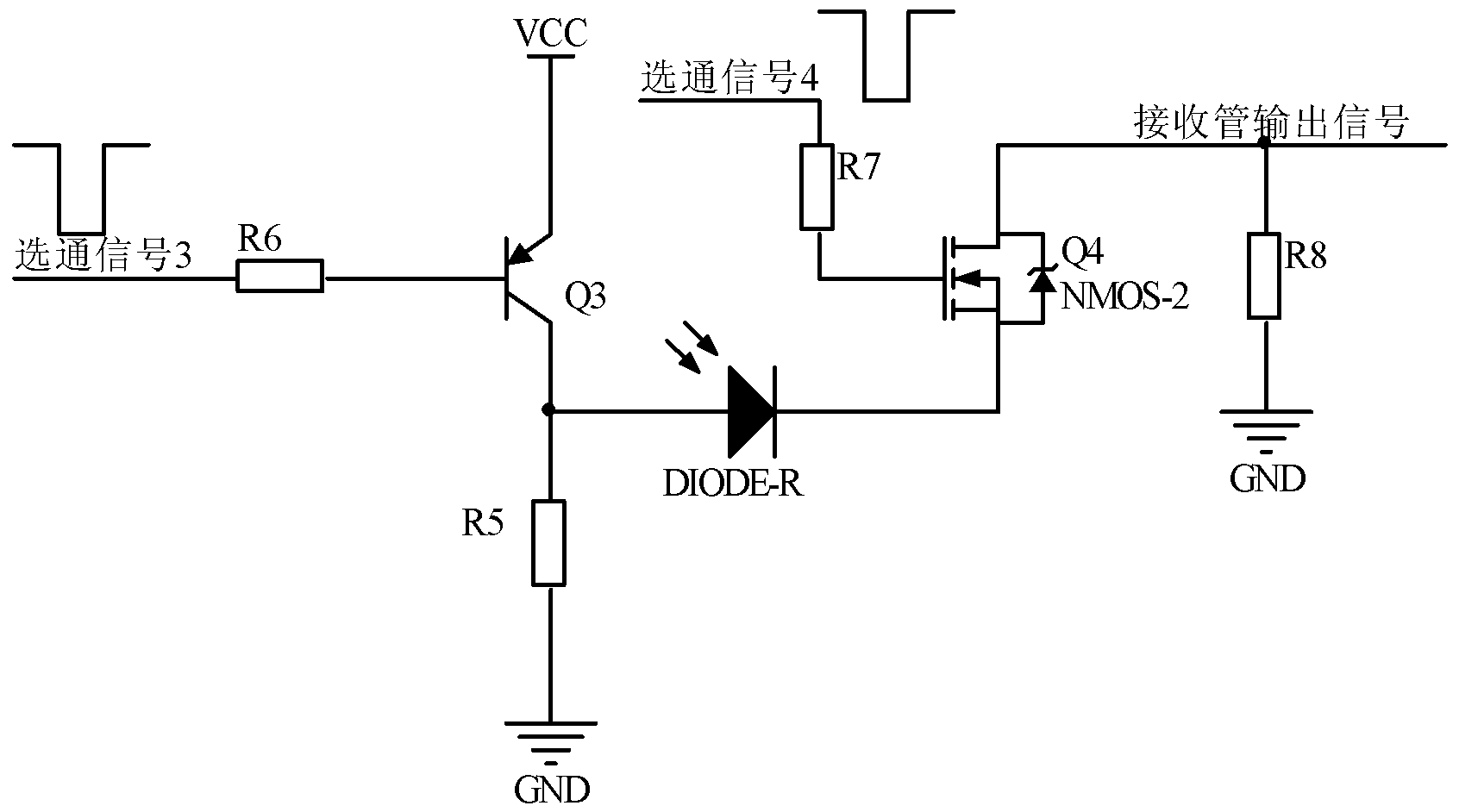
[0014] Such as figure 1 Shown. The infrared emission circuit of the touch panel is composed of infrared emission tube T, PNP Darlington tube Q1, NPN Darlington tube Q2, resistors R1, R2, R3, R4, and strobe signal 1 and strobe signal 2, at the same time to ensure symmetry For the two Darlington tubes, pairs of Darlington tubes with the same parameters are selected. When strobe signal 1 appears low level and strobe signal 2 appears high level, Darlington transistors Q1 and Q2 are all turned on (all described here are saturated conduction states, as long as R1, R2, and R3 are selected reasonably The resistance value of R4 can reach the required saturated conduction) The infrared emitting tube is in the conducting state, which is the normal working state of the infrared emitting tube; due to the relationship of the circuit structure, the strobe signal 1 and the strobe signal 2 are both It is a common signal that is connected to other infrared transmitting tubes. If there is no res...


PUM


Abstract

The invention discloses a hardware driving method suitable for a large-sized infrared touch screen. Infrared emission diodes and infrared reception diodes are densely distributed on the lower surface of the infrared touch screen; a whole circuit comprises a line gate module, an infrared emission module, an infrared reception module, an amplification circuit module and a processing chip. The line gate module is provided by a logic chip; an infrared emission circuit adopts a driving method of a Darlington tube and a current limiting resistor so as to enhance the luminous intensity, the problem that the driving capability is not strong under the condition of large size can be solved, and the competition and risks can be effectively avoided; an infrared reception circuit adopts a method of a triode and an MOSFET (Metal-Oxide-Semiconductor Field Effect Transistor) for providing receiving signals for an amplifier, effective transmission of weak signals can be realized, and after the signals are subjected to amplification filtering processing, the signals are sent to an MPU (Microprocessor Unit) for computation so as to obtain touch point coordinates.

Description

Technical field [0001] The invention relates to the field of multi-point touch screens, in particular to a hardware driving method suitable for large-size infrared touch screens. Background technique [0002] With the increase of multimedia information query equipment, people are talking about touch screens more and more, because the development of touch screens is not only suitable for the needs of multimedia information query national conditions, but also has many advantages such as sturdiness, fast response speed, space saving, and easy communication. . With the development of technology, touch screens have also evolved from traditional single-point touch to multi-point touch. Currently on the market, touch screens that use acoustics and other material science technologies have their insurmountable barriers, such as damage and aging of a single sensor, fear of contamination of the touch interface, destructive use, and complicated maintenance. The infrared touch screen h...

Claims


Application Information

Patent Timeline
Patent Type & Authority Applications(China)
IPC IPC(8): G06F3/042
Inventor 胡跃辉李小哲吕国强于芳芳刘志民
Owner HEFEI UNIV OF TECH
Learn More