
Mounting structure and mounting method

A technology of installation structure and installation method, which is applied in the direction of circuit devices, electrical components assembled printed circuits, printed circuits, etc., can solve the problems such as difficult to suppress "sounding" and achieve the effect of suppressing ringing

Active Publication Date: 2014-01-01
MURATA MFG CO LTD
View PDF5 Cites 11 Cited by
  • Summary
  • Abstract
  • Description
  • Claims
  • Application Information

AI Technical Summary

Problems solved by technology

However, high-permittivity dielectric ceramics, such as barium titanate, which are commonly used in large-capacity laminated ceramic electronic components, are materials that inevitably undergo electric field-induced deformation, making it difficult to suppress "ringing"

Method used


Image

  • Mounting structure and mounting method
  • Mounting structure and mounting method
  • Mounting structure and mounting method

Examples


Embodiment Construction

[0035] Hereinafter, embodiments of the multilayer capacitor of the present invention will be described with reference to the drawings.

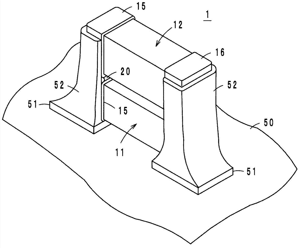
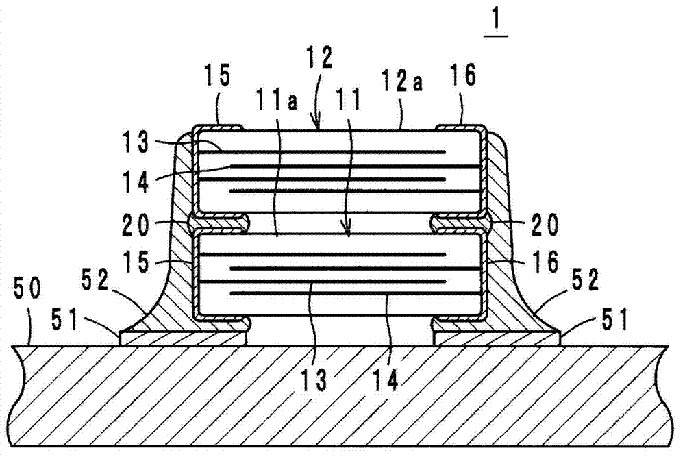
[0036] Such as figure 1 and figure 2 As shown, the mounting structure 1 as an embodiment is constituted as follows: a second ceramic electronic component (second ceramic capacitor 12) is mounted on a first ceramic electronic component (first ceramic capacitor 11), and the first ceramic electronic component is bonded by solder 20. The external electrodes 15 , 16 of the electronic component and the second ceramic electronic component are joined to each other, and the external electrodes 15 , 16 are joined to pads 51 formed on the surface of the circuit board 50 via solder 52 .

[0037] In this mounting structure 1 , the solder 52 wets up to the external electrodes 15 , 16 of the upper ceramic capacitor 12 . It should be noted that, when the joint strength of the ceramic capacitors 11 and 12 by the solder 20 is sufficient, the joint to the pa...


PUM


Abstract

A mounting structure includes a first ceramic electronic component including a ceramic body including internal electrodes and outer electrodes. When a voltage is applied to the outer electrodes, the ceramic body is strained with a first strain amount, and a second ceramic electronic component including a ceramic body including internal electrodes and outer electrodes. When a voltage is applied to the outer electrodes, the ceramic body is strained with a second strain amount greater than the first strain amount. The second ceramic electronic component is arranged above the first ceramic electronic component, and the first and second ceramic electronic components are connected to each other via each other's outer electrodes. The first ceramic electronic component to which the second ceramic electronic component is connected is connected to a land on a circuit substrate via the outer electrodes of at least the first ceramic electronic component.

Description

technical field [0001] The invention relates to a mounting structure and a mounting method, in particular to a structure and a method for mounting ceramic electronic components on a circuit substrate. Background technique [0002] Conventionally, in a multilayer capacitor in which a dielectric layer and a capacitor electrode are stacked, when a voltage containing a ripple component is applied, an electric field-induced strain occurs in the capacitor portion, and the stack expands and contracts. With the advancement of miniaturization and thinning of multilayer capacitors, the voltage applied to each dielectric body has increased, and electric field-induced deformation has become impossible to ignore. When the multilayer capacitor mounted (soldered) on the circuit board generates stretching vibration, it is transmitted to the circuit board to vibrate the circuit board. When the frequency falls in the audible range, that is, 20 Hz to 20 kHz, it is recognized as "sounding" by t...

Claims


Application Information

Patent Timeline
Patent Type & Authority Applications(China)
IPC IPC(8): H01G2/06
CPCH05K1/0216H05K3/30H05K1/181H05K3/3442H05K2201/10515H05K2201/2045Y10T29/4913Y02P70/50H01G2/06H01G4/12
Inventor 堂垣内一雄
Owner MURATA MFG CO LTD
Learn More