
Current-mode DC-DC converter

A converter and current mode technology, applied in the direction of conversion equipment without intermediate conversion to AC, can solve the problems of reducing the integration of conversion chips, increasing the PCB space of printed circuit boards, and difficulty in integration, so as to simplify the pins of conversion chips , reduce the PCB area, and achieve the effect of complete integration

Active Publication Date: 2014-01-01
深圳德信微电子有限公司
View PDF7 Cites 13 Cited by
  • Summary
  • Abstract
  • Description
  • Claims
  • Application Information

AI Technical Summary

Problems solved by technology

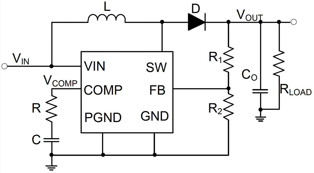
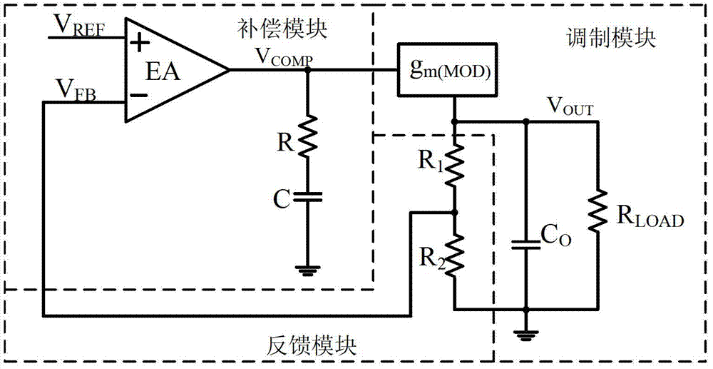
Considering factors such as cost and packaging, this compensation structure is difficult to integrate, and this large capacitor can only be placed externally by adding a chip pin, such as figure 1 shown
This not only reduces the integration level of the conversion chip, but also increases the space of the printed circuit board PCB

Method used


Image

  • Current-mode DC-DC converter
  • Current-mode DC-DC converter
  • Current-mode DC-DC converter

Examples


Embodiment Construction

[0039] The present invention will be further described below in conjunction with accompanying drawings and embodiments thereof.

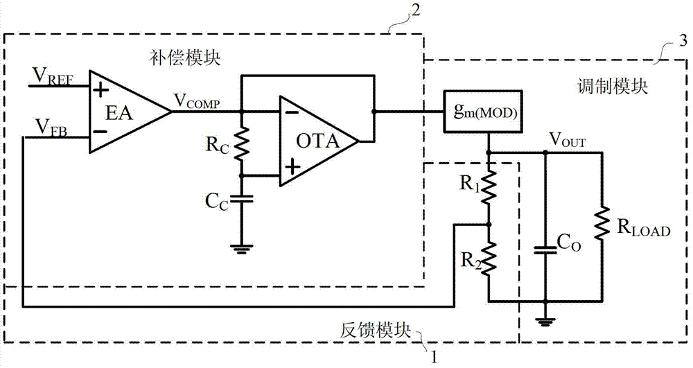
[0040] refer to image 3 , the current mode DC-DC converter of the present invention includes a feedback module 1, a compensation module 2 and a modulation module 3;

[0041] The feedback module 1 is used to set the converter output voltage V OUT It consists of two feedback resistors in series, and the common terminal of these two feedback resistors outputs the feedback voltage V FB to compensation module 2.

[0042] The compensation module 2 includes an error amplifier EA, a compensation resistor R C , compensation capacitor C C And the transconductance amplifier OTA, the error amplifier EA, its non-inverting input terminal is connected to the reference voltage V generated inside the converter REF , whose inverting input is connected to the feedback voltage V FB , and its output terminal outputs the comparison signal V COMP to modulation blo...


PUM


Abstract

The invention discloses a current-mode DC-DC converter which mainly solves the problem that an existing converter compensating circuit is difficult to integrate. The current-mode DC-DC converter comprises a feedback module (1), a compensating module (2) and a modulation module (3). The feedback module (1) is used for setting an output voltage of the converter, the compensating module (2) utilizes a transconductance amplifier to sample and amplify a current of a small capacitor so that capacitance multiplication can be achieved, and a compensating capacitance value is reduced greatly; meanwhile, the compensating module (2) compares a feedback voltage VFB and a reference voltage VREF so that an error signal VCOMP can be obtained, the modulation module (3) compares the error signal with a fixed ramp signal so that a driving signal with the corresponding duty ratio can be obtained, and regulation of the output voltage of the transformer is achieved. The compensating module (2) of the current-mode DC-DC converter can be completely integrated in a conversion chip, a pin of the conversion chip is simplified, the area of a PCB is reduced, and the current-mode DC-DC converter can be used in various portable devices small in size.

Description

technical field [0001] The invention belongs to the technical field of electronic circuits, and relates to an analog integrated circuit, in particular to a current mode DC-DC converter. Background technique [0002] With the integration of various functions such as color screens, games, built-in CMOS lenses, etc. in battery-operated portable devices such as mobile phones, PDAs, digital cameras and music players MP3, power requirements and battery life have also become design must-haves. The DC-DC converter is widely used in the above-mentioned portable devices due to its advantages of high efficiency, low power consumption and flexible output voltage conversion, ie flexible buck, boost and negative voltage conversion. [0003] Pulse width modulation PWM type DC-DC converter mainly has two kinds of control schemes: voltage mode and current mode. Among them, in the voltage mode control, the duty cycle of the converter is proportional to the error value between the actual outp...

Claims


Application Information

Patent Timeline
Patent Type & Authority Applications(China)
IPC IPC(8): H02M3/06
Inventor 来新泉叶强邵丽丽
Owner 深圳德信微电子有限公司
Learn More